


4 - 7
MELSEC-
A
4 PROCEDURES AND SETTINGS BEFORE OPERATION
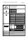
No. Name Details
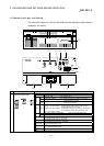
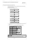
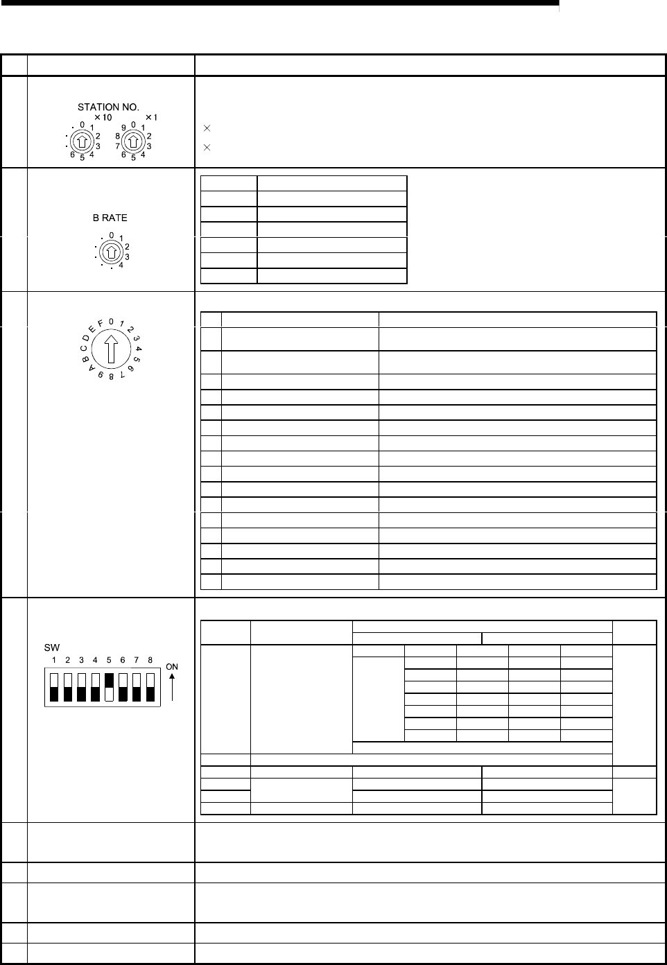
(2) Station No. setting switch Set the module's station No. (Default setting: 0)
Setting range: 1 to 64 (0: Master module)
" 10" sets the 10th place of the station No..
"
1" sets the 1st place of the station No..
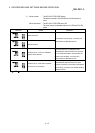
Setting Transmission speed
0 156kbps
1 625kbps
22.5Mbps
35Mbps
4 10Mbps
- Setting error
Set the module's transmission speed (for data
link)
(Default setting: 0)
(3) Data link transmission speed
setting switch
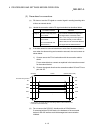
Set the module's operation state. (Default setting: 0)
No. Name Setting details
0
On-line mode (using
transmission/reception buffer)
Mode for on-line communication.
Set when using the transmission/reception buffer.
1
On-line mode (using buffer memory
automatic update function)
Mode for on-line communication.
Set when using the buffer memory automatic update function.
2 Not used Setting error ("RUN" LED turns OFF.)
3 Not used Setting error ("RUN" LED turns OFF.)
4 Use not possible –
5 Not used Setting error ("RUN" LED turns OFF.)
6 Not used Setting error ("RUN" LED turns OFF.)
7 Not used Setting error ("RUN" LED turns OFF.)
8 Not used Setting error ("RUN" LED turns OFF.)
9 Not used Setting error ("RUN" LED turns OFF.)
A Not used Setting error ("RUN" LED turns OFF.)
B Not used Setting error ("RUN" LED turns OFF.)
C Not used Setting error ("RUN" LED turns OFF.)
D Hardware test mode Mode for confirming that module runs independently.
E Not used Setting error ("RUN" LED turns OFF.)
F Not used Setting error ("RUN" LED turns OFF.)
(4) Mode setting switch
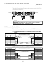
Set the RS-232-C transmission specifications.
Setting switch state
No. Setting details
ON OFF
Default
setting
SW 1 2 3
0 0 0 300bps
1 0 0 600bps
0 1 0 1200bps
1 1 0 2400bps
0 0 1 4800bps
1 0 1 9600bps
0 1 1 19200bps
SW1 to 3 Transmission speed
0:OFF 1:ON
SW4 Not used
OFF
SW5 Data bit length 8 7 ON
SW6 Yes No
SW7
Parity bit
Even Odd
SW8 Stop bit length 2 1
OFF
(5) RS-232-C transmission
specifications setting switch
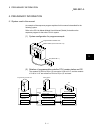
(6) Data link terminal block Connect a CC-Link dedicated cable for power supply and data link. (2-piece terminal
block)
(7) RS-232-C interface Connect an RS-232-C cable for connection with external device.
(8) General-purpose input/output
terminal block.
Connect the input/output wire.
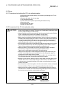
(9) Reset switch Returns to the power ON status.
(10) Connector Use prohibited.