4 - 6
MELSEC-
A
4 PROCEDURES AND SETTINGS BEFORE OPERATION
4.4 Names of each part, and settings
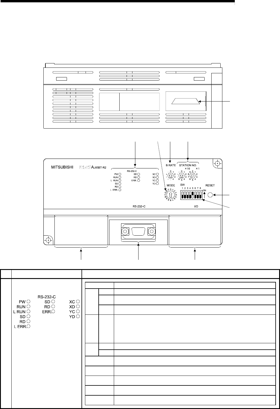
The names of the parts in the R2, the LED details, and the settings for each switch are
explained in this section.
(10)
(1) (3) (2)
(
7
)
(
6
)
(
8
)
(9)
(5)
(4)
No. Name Details
LED name Details
PW
ON: Power is ON. OFF: Power is OFF.
RUN
ON: Operating normally OFF: Power (24VDC) is OFF, WDT error is occurring or
the switch setting is incorrect.
De-
fault
state
L RUN
ON: Communicating normally OFF: Communication stopped (Time over error) or the
switch setting is incorrect.
State L ERR.
ON: Any transmission speed or station number out of range is set.
Flickering at constant intervals : The transmission speed or station number has been
changed after the power is turned on.
Flickering not constant intervals : The terminating resistor is not connected. The module or
CC-Link dedicated cable is being affected by noise.
OFF: Communicating normally
SD ON, Flashing: Data link Sending data OFF: Data link Not sending data
Others
RD ON, Flashing: Data link Receiving data OFF: Data link Not receiving data
XC, XD
ON: General-purpose input (XC, XD) is ON.
OFF: General-purpose input (XC, XD) is OFF.
YC, YD
ON: General-purpose output (YC, YD) is ON.
OFF: General-purpose output (YC, YD) is OFF.
RS-232-C SD
ON, Flashing: Sending RS-232-C data
OFF: Not sending RS-232-C data
RS-232-C RD
ON, Flashing: Receiving RS-232-C data
OFF: Not receiving RS-232-C data
RS-232-C
ERR.
ON: RS-232-C transmission error OFF: No error
(1) Operation display LEDs


