


8 - 24
MELSEC-
A
8 OTHER FUNCTIONS
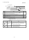
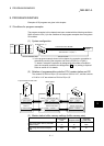
8.10 Confirming the R2 switch states and software version
By reading the R2 buffer memory shown below, the R2 switch state and software
version can be confirmed.
This is effective for confirming the state when the R2 switch settings are correct but the
operation is incorrect.
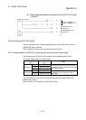
When using the buffer memory automatic update function to read, refer to section 5.6.
Refer to section 5.7.3 when using the transmission/reception buffer.
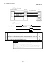
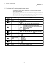
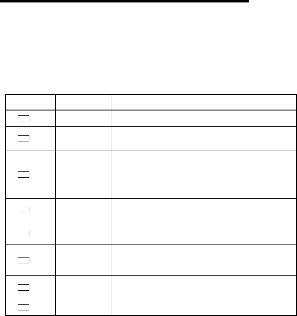
R2 buffer memory
address
Name Details
R2
1A0H
Station No. setting
switch
The state of the R2 station No. setting switch is stored.
1 to 64 : Station No.
R2
1A1H
Data link transmission
speed setting switch
The state of the R2 data link transmission speed setting switch is stored.
(Unit: kbps)
156, 625, 2500, 5000, 10000 : Set data link transmission speed
R2
1A2H
Mode setting switch
The state of the R2 mode setting switch is stored.
0
H : On-line mode (using transmission/reception buffer)
1
H : On-line mode (using buffer memory automatic update function)
2H to CH: Not used or Use not possible
DH : Hardware test mode
E
H, FH : Not used
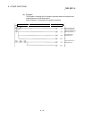
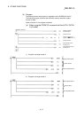
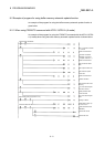
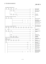
R2
1A3H
RS-232-C
transmission speed
The transmission speed set in the R2 is stored. (Unit: bps)
300, 600, 1200, 2400, 4800, 9600, 19200 : Set RS-232-C transmission
speed
R2
1A4H
RS-232-C data bit
length
The data bit length set in the R2 is stored.
7 : 7 bits
8 : 8 bits
R2
1A5H
RS-232-C parity bit
validity
The validity of the parity bit set in the R2 is stored.
0 : No parity bit
1 : Odd parity bit
2 : Even parity bit
R2
1A6H
RS-232-C stop bit
length
The stop bit length set in the R2 is stored.
1 : 1 bit
2 : 2 bits
R2
1BFH
Software version
storage
The R2 software version is stored as an ASCII code.
41
H(A) to 5AH (Z) : R2 software version