8 - 7
MELSEC-
A
8 OTHER FUNCTIONS
(b) DC1/DC3 reception control
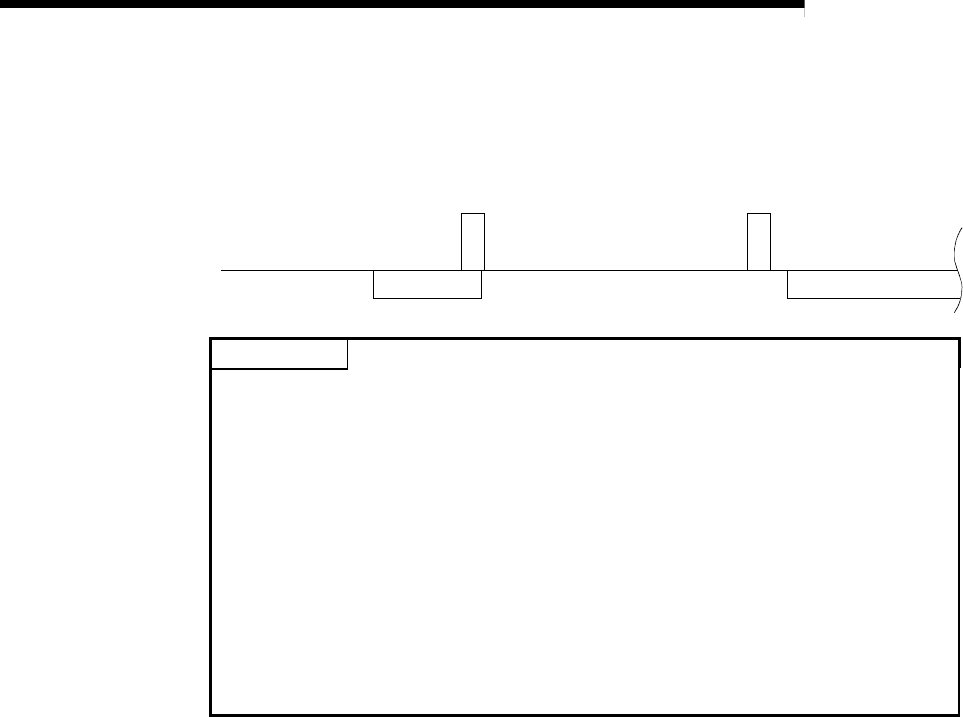
When the R2 receives the DC3 code, the transmission to the external
device is canceled. When the DC1 code is received, the transmission to the
external device is restarted.
D
C
1
D
C
3
External device side
R2 side
Data Data
POINT
(1) When the power is turned ON or the system is initialized, the DC1
transmission state (reception enable) and DC1 reception state (transmission
enable) are set.
Note that the R2 does not wait to transmit DC1 to the external device, or
receive DC1 from the external device.
(2) When carrying out DC code control, the DC1/DC3 code received from the
external device is not stored in the R2 reception area.
(3) The DC1 and DC3 codes are 11
H and 13H.
The DC1 and DC3 codes cannot be changed.
(4) When carrying out DC code control, if a DC code data (11
H, 13H) used for
the DC code control is contained in the transmission/reception data, use the
ASCII-BIN conversion function.
If the ASCII-BIN conversion function is not used, DC code data used for the
DC code control cannot be used.
(2) DTR/DSR signal control
The R2 notifies the external device whether the local station can receive data
with the DTR(ER) signal. Whether the external device can receive data is
confirmed with the DSR (DR) signal.
(a) DTR (ER) control
If the amount of space open in the OS reception area is less than 64 bytes,
the R2 turns OFF the DTR (ER) signal, and the external device cancels the
transmission to the R2.
When the reception data is read out from the programmable controller CPU
and the amount of space open in the OS reception area reaches 263 bytes
or more, the DTR (ER) signal is turned ON, and the transmission from the
external device to R2 is restarted.


