10 - 9
MELSEC-
A
10 TROUBLESHOOTING
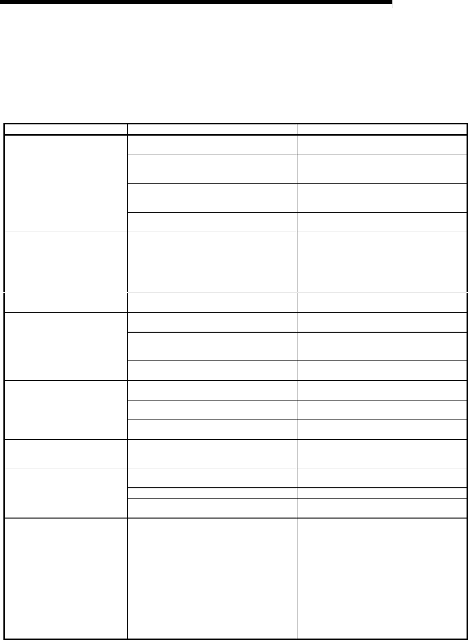
10.4 Troubleshooting per symptom
The troubleshooting for symptoms that occur during communication between the R2
and external device is shown below.
When a trouble occurs, check the R2 state, and check the items for the corresponding
items below.
Symptom Cause Remedy
The signal wire connection is incorrect.
Check whether the RD and SD are correctly
connected to the R2 and external device.
The external device side transmission control
signal is not ON.
Wire so that the transmission control signal such
as the R2 side "DSR" and "CS" are turned ON by
the external device side.
When carrying out flow control, the R2 OS
reception area open space is less than 64 bytes.
Carry out the reception process so that the open
space in the R2 OS reception area is 263 bytes
or more.
"RD" does not flicker even when a
statement is transmitted from the
external device.
The transmission speed settings do not match.
Match the R2 and external device transmission
speeds.
The transmission complete condition data has not
been received.
•
Check that the data with the fixed length set
on the R2 side has been transmitted from the
external device.
•
Check whether the end frame has been
transmitted when communicating with
registration frames.
"RD" flickered when the statement
was transmitted from the external
device, but the read request did not
turn ON
The transmission speed settings do not match.
Match the R2 and external device transmission
speeds.
The external device reception complete condition
data has not been transmitted.
Transmit data that satisfies the external device
reception complete conditions.
When carrying out flow control, the open space in
the external device OS reception area is
insufficient.
Carry out reception process with the external
device to increase the open space in the external
device OS reception area.
The statement was transmitted
from the R2, but it was not received
by the external device.
The transmission speed settings do not match.
Match the R2 and external device transmission
speeds.
The mode setting switch or transmission
specifications setting switch setting is incorrect.
Read the error code from the buffer memory,
check the error details, and correct the setting.
The R2 detected an error during data
transmission.
Read the error code from the buffer memory, and
remedy according to the error details.
The ERR.LED turns ON
The R2 detected and error during data reception.
Read the error code from the buffer memory, and
remedy according to the error details.
Communication is possible in some
cases, and not possible in other
cases.
The signal cable wiring has a contact fault. Replace the cable, or securely fix the connection.
The parity bit settings do not match.
Match the R2 and external device parity check
settings.
The stop bit length settings do not match. Match the R2 and external device stop bit size.
Non-recognizable data is
transmitted or received.
The transmission speed settings do not match.
Match the R2 and external device transmission
speeds.
It is not known whether the
communication error cause is on
the R2 side or external device side.
–—
Carry out the following test on the R2 or master
station side to check where the cause is.
1) Check the hardware.
•
The R2 must be securely mounted.
•
None of the module pins must be bent or
abnormal.
2) Test the R2 hardware. (Refer to section 4.6.)
•
There must be no error in the hardware
test.
3) Check the CPU state.
•
There must be no error to cause the CPU
operation to stop


