9 - 1
MELSEC-
A
9 PROGRAM EXAMPLES
9
9. PROGRAM EXAMPLES
Examples of R2 programs are given in this chapter.
9.1 Conditions for program examples
The program examples in this chapter have been created with the following conditions.
Refer to section 9.2.4 (1) for the conditions of the program examples when using three
R2 modules.
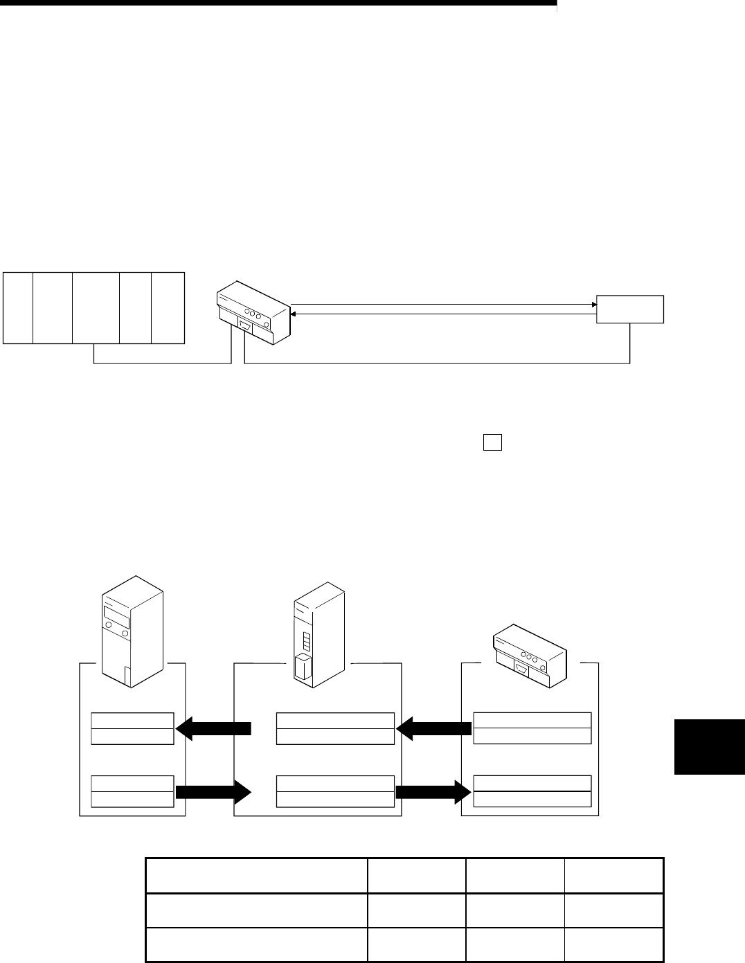
(1) System configuration
CPU
X/Y00 to
X/Y1F
AX42
X20 to
X5F
AY42
Y60 to
Y9F
Power
supply
Master
station
R2 (Station No. 1)
Transmission data: ABCDEF
External
device
Reception data: "Random data + CR (0DH)" or
"Random data + LF (0A
H)"
*1
CC-Link dedicated cable RS-232-C cable
*1 In the program example shown in this chapter, the reception completion is
detected by receiving the reception end frame (CR(0D
H) or LF(0AH)).
To detect a reception completion by designating the number of reception
data, the reception end data size designation (R2
111H) setting is required.
Refer to section 6.2 for details.
(2) Relation of programmable controller CPU, master station and R2
The contents of RXn0 to RX(n+1)F are read into X100 to X11F, and the contents
of Y100 to Y11F are written into RYn0 to RY(n+1)F.
X100 to X10F
X110 to X11F
Y100 to Y10F
Y110 to Y11F
RXn0 to RXnF
RX(n+1)0 to RX(n+1)F
E0
H
E1
H
RYn0 to RYnF
RY(n+1)0 to RY(n+1)F
160
H
161
H
R2
RXn0 to RXnF
RX(n+1)0 to RX(n+1)F
RYn0 to RYnF
RY(n+1)0 to RY(n+1)F
Programmable Controller CPU
Master station
Device Y
Device X Address Remote input (RX)
Remote output (RY)
Remote input (RX)
Remote output (RY)
(3) Master station buffer memory settings (buffer memory size)
Transmission
buffer
Reception buffer
Automatic
update buffer
When using buffer memory automatic
update function
0
H 0H 600H
When using transmission/reception
buffer
200
H 200H 0H


