


EN-27
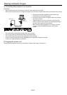
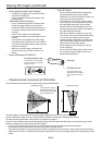
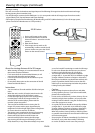
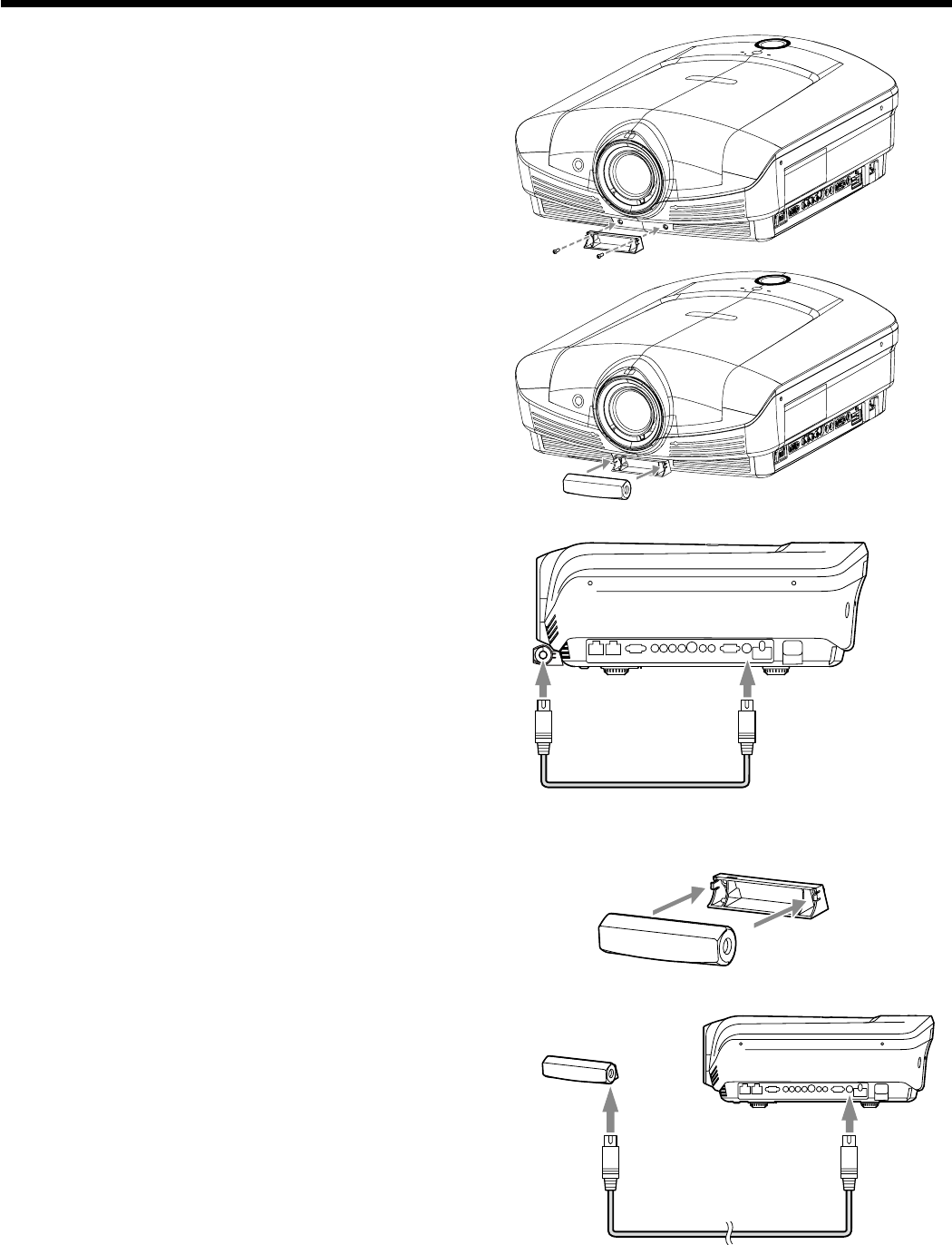
• Placing the 3D Emitter in an arbitrary place
Viewing 3D images (continued)
Preparation:
Turn o the power of the projector.
1. Put the Infra-red transmission part of the 3D Emitter
into the base part.
2. Secure temporarily the 3D Emitter in an arbitrary
place (such as the wall around the screen).
3. Connect the 3D emitter terminal on the 3D Emitter to
the 3D EMITTER terminal on the projector using the
supplied mini DIN 5-pin cable (15 m).
4. Prepare the 3D Glasses.
5. Adjust the position and angle of the 3D Emitter so
that the 3D Glasses can receive the infra-red signal.
• Aftercompletingtheadjustment,xthe3DEmitter
rmly using the supplied double-sided tape, etc.
To 3D EMITTER
terminal
To 3D Emitter
terminal
Mini DIN 5-pin cable (1 m)
To 3D
EMITTER
terminal
To 3D
Emitter
terminal
Mini DIN 5-pin cable (15 m)
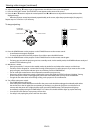
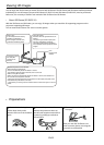
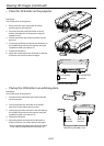
• Place the 3D Emitter on the projector
Preparation:
Turn o the power of the projector.
1. Remove the lens caps covering the 3D Emitter
attaching part on the projector.
2. Secure the base part of the 3D Emitter to the 3D
Emitter attaching part on the projector using the
supplied screws.
3. Put the transmission part of the 3D Emitter into the
base part.
4. Connect the 3D Emitter terminal on the 3D Emitter to
the 3D EMITTER terminal on the projector using the
supplied mini DIN 5-pin cable (1 m).
5. Prepare the 3D Glasses.
6. Adjust the vertical angle of the 3D Emitter so that the
3D Glasses can receive the infra-red signal.