


9
High-bandwidth Digital Content Protection
(HDCP)
HDCP is a system designed to protect the outputs of
a DVI device from being copied. The protection can
be applied in various ways.
• Unrestricted copies
• Limited number of copies
• Limited use of copies
• No copies
Since this is a optional element of DVI, both the host
device and the receiving device must be properly
equipped to function and provide the protected link
between them. There are three parts within the con-
tent protection scheme.
• Authentication… The host and receiver
exchange data to confirm the receiver is
authorized to receive the protected data.
• Encryption/Decryption… After the host
has verified the receiver, "keys" are provided
that will allow the receiver to decrypt the
data sent.
• Renewability… Each receiver is given both
a secret code and a non-secret identification
number. If the host determines the secret
keys have been tampered with, the receiver
is denied authentication.
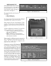
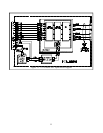
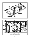
The authentication process occurs over the DDC I
2
C
bus shown in Figure 11. After authentication, the
encrypted video data is applied to the TMDS encoder.
The encrypted data sent over the DVI interface is
then immune to "eavesdropping." Only the autho-
rized display device can reverse the encryption af-
terwards.
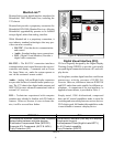
Hot Plug Detect (HPD)
Another part of the plug and play package is the
VESA standard Hot Plug Detect. A dedicated pin
on the DVI connector is used by the display to let
the host know it is plugged in. When the host de-
vice detects a High condition greater than 2.4 VDC
(typically 5.0 VDC), it will read the EDID and start
operation. If the potential falls below 2.0 VDC the
TMDS transmitter is stopped.
Digital Monitor Power Management (DMPM)
DMPM allows several different levels of power man-
agement by detecting the presence of EDID and/or
TMDS activity. One pin on the DVI connector is
provided so the host can supply a 5 V source. The
display has the option to use this supply to keep the
DDC capable while the monitor is off.
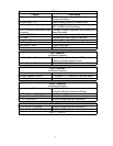
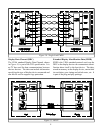
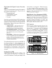
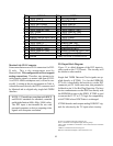
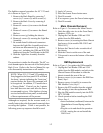
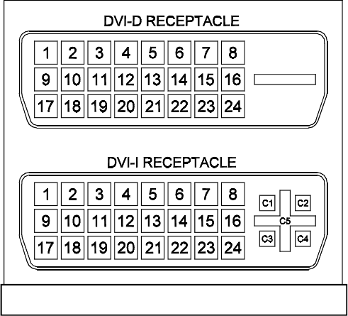
DVI Connectors
There two types of DVI receptacles shown in Fig-
ure 12, DVI-D and DVI-I. Pin assignments are de-
tailed in Table 6. It should be noted, the additional
pins, C1-C5, arranged in the + shape on the DVI-I
receptacle, are provided for analog signals. No DVI-
A connector is shown because DVI-A is generally
associated with adapting VGA connectors to DVI-I.
Figure 12: DVI Receptacles