


3-4
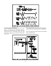
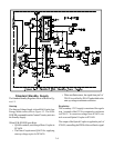
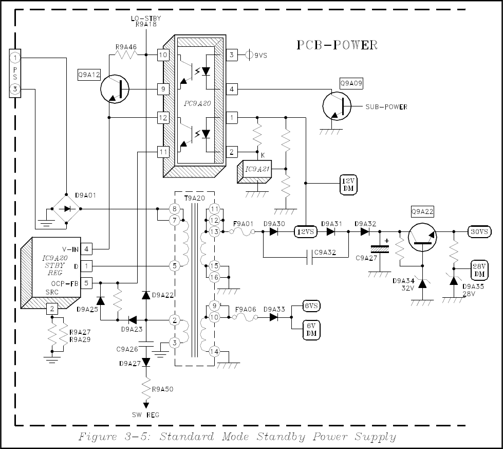
Standard Standby Supply
The Standard Standby Regulator circuit is shown in Fig-
ure 3-5.
Start-up
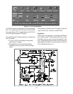
The Start-up Voltage Supply is from R9A18 in the Low
Energy Mode circuit, refer to Figure 3-2. The SUB-
POWER command from the Control Circuitry activates
the Standby Supply.
When SUB-POWER goes High:
• Q9A09 conducts, activating a Photo Coupler in
PC9A20.
• The Photo Coupler turns Q9A12 On, supplying
start-up voltage to pin 4 of IC9A20.
• When oscillation starts, the signal from pin 2 of
T9A20 is rectified by D9A22 and added to the
start-up voltage to maintain oscillation.
Regulation
The secondary 12VS supply is monitored for regula-
tion. A sample of the 12VS is compared to a reference
in IC9A21. A correction voltage from IC9A21 con-
trols a second Optical Coupler in PC9A20.
The output of the Optical Coupler is applied to pin 5 of
IC9A20, controlling the PWM of the oscillator's signal.