


6-7
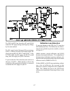
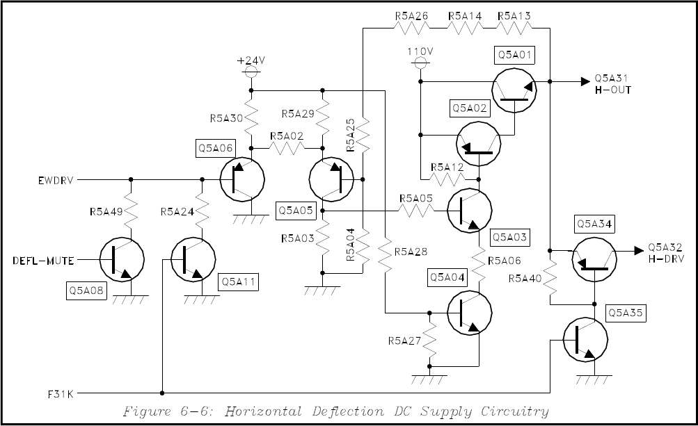
The DEFL-MUTE line from the µPC and Q5A08
reduce the DC supply during scan frequency change
by the same method.
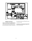
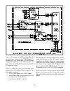
The DC supply for the Horizontal Drive transistor,
Q5A32, is derived from the Horizontal Output DC
supply through R5A36, R5A37 and Q5A34. In the
31.5 kHz mode, the DC supply for Q5A32 would
drop, since the supply for Q5A31 decreases.
To prevent this the 31K control line also connects to
the base of Q5A35. When Q5A35 is driven into
conduction, the conduction of Q5A34 is increased
to maintain the DC supply for Q5A32.
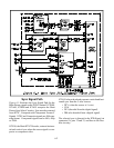
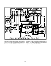
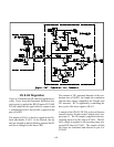
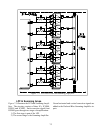
Deflection Loss Detection
To prevent damage to the CRTs, the TV must shut
Off if deflection is lost. The Deflection Loss Detec-
tion circuit is similar to previous models, as shown
in Figure 6-7.
Q4B01 monitors vertical deflection, and Q5A38
monitors horizontal deflection. The conduction of
both transistors holds their respective collector volt-
age below the forward bias point of the diode in their
collector circuit's (D4B04 or D5A12).
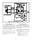
If either Q4B01 or Q5A38 stop conducting, indicat-
ing a loss of deflection, the increase in that
transistor’s collector voltage drives the V-Blank line
High. The V-Blank line goes to the CRT Protect
circuitry and immediately removing all drive to the
CRTs.