


6-2
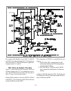
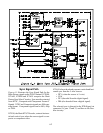
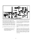
Sync Signal Path
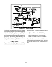
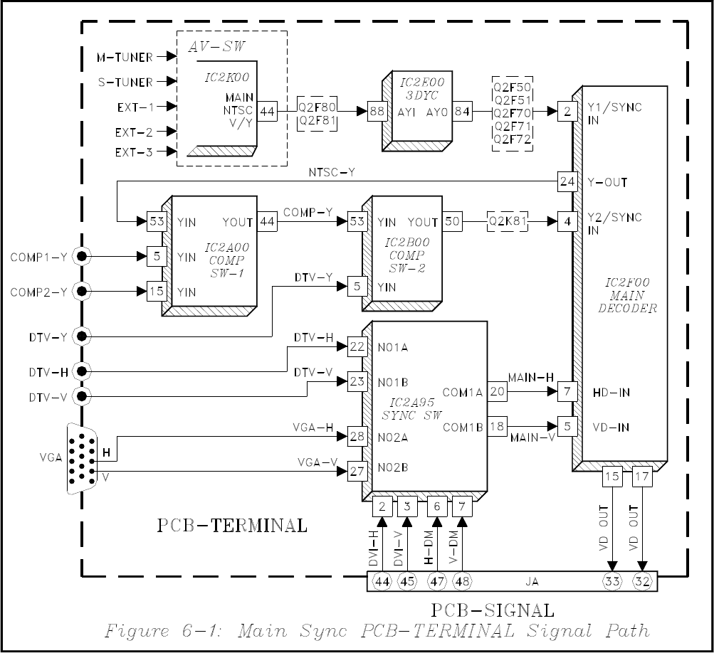
Figure 6-1 illustrates the Sync Signal Path for the
Main Picture signals on the PCB-Terminal. IC2K00,
IC2A00, IC2B00 and IC2A95 comprise the Main
Picture Sync Select Circuitry. Sync must be extracted
from NTSC, Composite and Component Format Y
Signals. NTSC and Composite signals are 480i scan-
ning format. Component signals can be 480i, 480p
or 1080i.
IC2F00, the Main NTSC Decoder, extracts horizon-
tal and vertical sync when the source signal is com-
posite or component video.
IC2A95 selects the already seperate vertical and hori-
zontal sync from the 5-wire sources.
• DTV (when the source is 5-wire)
• VGA
• DVI (decoded from the digital signal)
• DM (also decoded from a digital signal)
The selected sync is directed to the PCB-Signal via
connector JA, pins 32 and 33, and then to the Dou-
bler circuitry.