


3-2
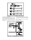
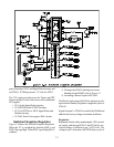
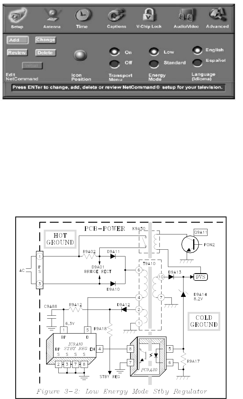
A 132 kHz internal Oscillator drives an internal Output
FET. The signal from the FET at pin 5 of IC9A10,
drives transformer T9A10. Signal from pin 10 of T9A10
is rectified, generating the 9VS supply.
The signal from pin 2 of the transformer is rectified and
takes two paths:
1) To pin 1 of IC9A10, adding to an internally
generated 6.3V supply.
2) Through R9A18 to the Standard Standby
Regulator circuit, serving as a start-up voltage
source.
For regulation a sample of the 9VS supply is fed back
to pin 4 of IC9A10, via D9A14 and PC9A20.
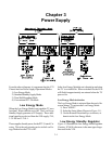
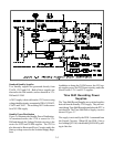
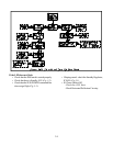
Regulation
IC9A10 does not regulate by controlling the PWM of
the oscillator signal. Under normal load, some of the
132 kHz cycles are removed and not applied to the
FET. Under light loads, more of the cycles are removed,
and during heavy loads few, if any cycles are removed.
This is illustrated in Figure 3-3.
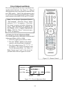
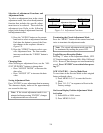
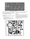
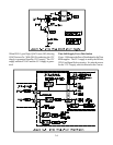
Figure 3-1: User Setup Menu