


3-7
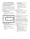
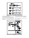
gence Generator, 3DYC and Signal Select circuitry, and
to IC2E65. IC2E65 generates 2.5 Volts for 3DYC.
The 12V supply provides power for Tuners and CRT
Protect circuitry. It also is the source of four additional
DC Supplies:
• 9V-1 for the Signal Select circuitry
• 5V-DECOD for the NTSC Decoders.
• 9V-2 for CRT Drive, MCS, Signal Select and
Doubler circuitry.
• 5V-DAC for the Convergence DAC circuits.
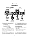
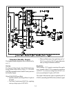
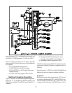
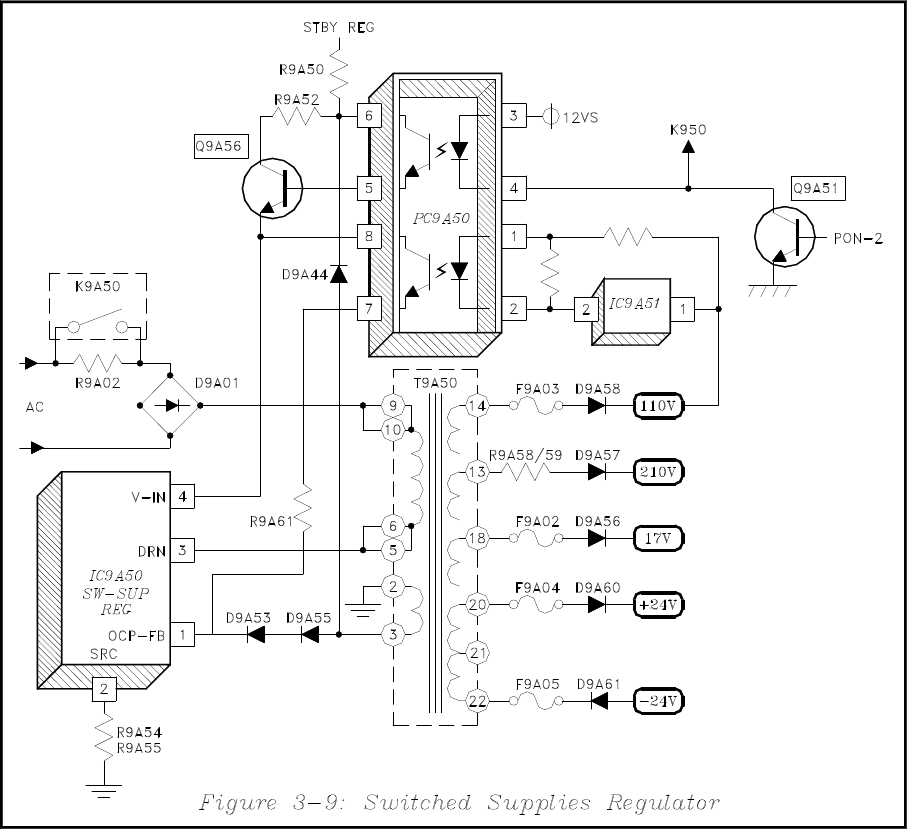
Switched Supplies Regulator
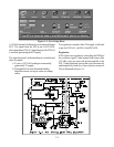
Figure 3-9 shows the Switched Supplies Regulator.
When the TV is switched On, both the PON-1 and
PON-2 lines go High. When PON-2 goes High Q9A51
conducts:
1) Closing relay K9A50, shorting out current
limiting resistor R9A02, refer to Figure 3-2.
2) Activating a Photo Coupler in PC9A50.
The Photo Coupler turns Q9A56 On, and start up volt-
age from the Standby Regulator is applied to pin 4 of
IC9A50.
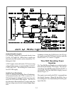
Signal from pin 3 of T9A50 is rectified by D9A44 and
added to the start up voltage to maintain oscillation.
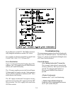
Regulation
Regulation is achieved by monitoring the 110V second-
ary supply, and through IC9A51 and PC9A50 a cor-
rection voltage is fed back to pin 1 of IC9A50. The
voltage at pin 1 determines the PWM (duty cycle) of