


5-1
Chapter 5
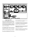
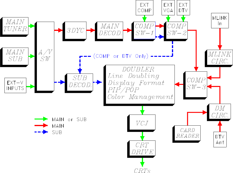
Video/Color Circuitry
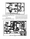
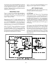
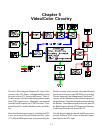
The above block diagram illustrates the Video/Color
circuitry in the V23 chassis. Although initially it looks
the same as in the V21, there are differences. The A/V
Switch circuitry still selects main and sub picture signals
from NTSC signal sources. Although it’s not apparent
from the Block Diagram, the NTSC Decoders, Com-
ponent Switch ICs, and the Doubler circuitry are differ-
ent.
Note that all main picture sources, including the DTV
Tuner, are processed by the Doubler circuitry. In the
V21, 480p and DM signals only were processed by the
Doubler circuitry when a display other than Standard
format was selected, or when PIP/POP was activated.
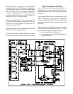
The new improved Color Management (ColorPerfect
TM
)
circuitry is in the Doubler circuitry and it now processes
all signal sources. Therefore all signals must pass through
the Doubler. Two additional signal sources are shown in
the Block Diagram, MLink (DVI) Input, and a Memory
Card Reader located in the front of the TV.
Also the diagram indicates that the Sub Picture source
can only be from a NTSC source, an External Compo-
nent Input or the DTV input.