


5-2
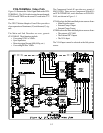
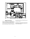
PCB-TERMINAL Video Path
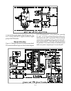
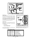
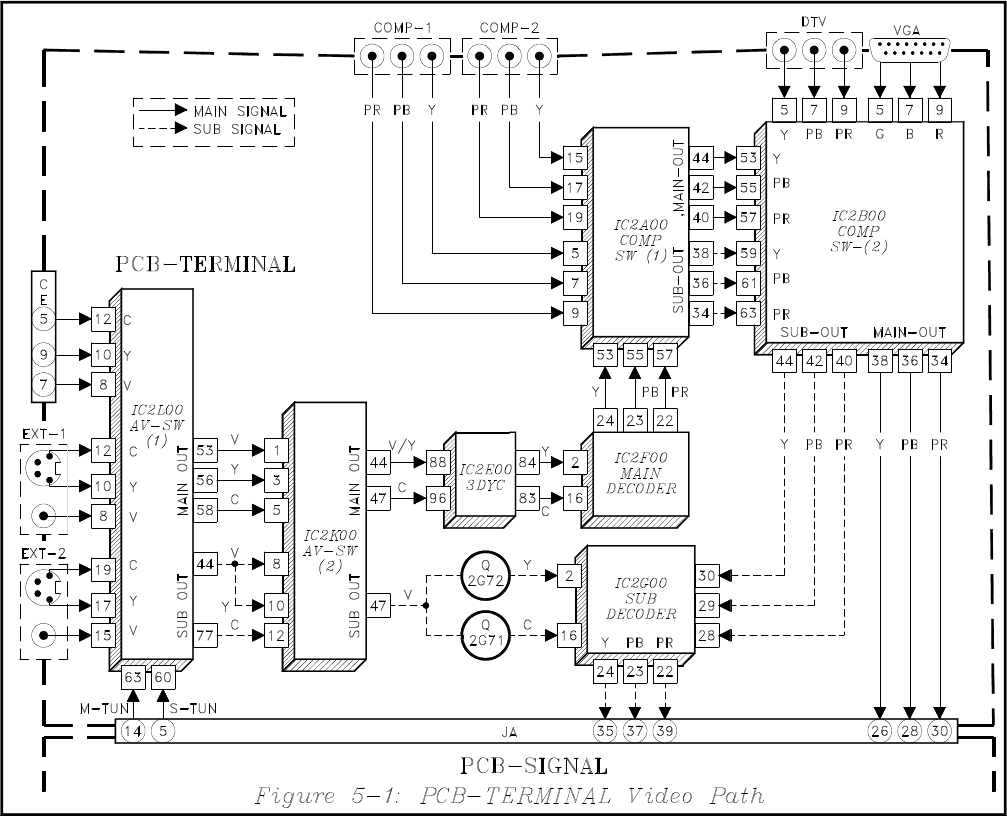
Figure 5-1 illustrates the Video Signal Path on the PCB-
TERMINAL. The AV-Switch circuitry has not changed,
IC2L00 and IC2K00 are the same ICs used in the V21
chassis.
The 3DYC Motion Adaptive Come Filter provides a
clean separation of luminance (Y) and chroma (C) sig-
nals.
The Main and Sub Decoders are new, generic
#TA12440AF. Their functions include:
• Converting NTSC to YPbPr.
• Sync Separation
• Detecting signal format (480i, 480p, etc.)
• Converting RGB to YPbPr.
The Component Switch ICs are also new, generic #
MM1519XQ. There are two Component Switch ICs
on PCB-TERMINAL, and a third one on PCB-SIG-
NAL, not shown in Figure 5-1.
IC2A00 selects the Main and Sub picture sources from:
• Main Decoder output
• External Comp-1 Input
• External Comp-2 input
IC2B00 selects the Main and Sub picture sources from:
• The outputs of IC2A00
• The External DTV Inputs
• The VGA Input
The VGA Input cannot be selected as the Sub picture
source.