


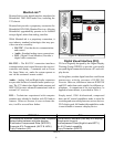
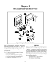

1-2
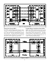
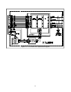
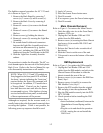
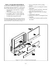
The lightbox removal procedure for 48” V23 mod-
els is shown in Figure 1-1.
1. Remove the Back Board by removing 7
screws (a), 2 screws (b) and 8 screws (c).
2. Remove the Back Cover by removing 8
screws (d).
3 Remove 4 screws (e) to remove the Board
Slide.
4. Remove 8 screws (f) to remove the Board
Shelves.
5. Remove screw (g) holding the chassis.
6. Remove 4 screws (h) securing the Light Box
Assembly.
7. Be certain that all cables and connectors
between the Light Box Assembly and exter-
nal items are disconnected (e.g. speaker
plugs, etc.), including the USB and IEE1394
connectors from the Card Reader to the DM.
8. Slide the Light Box Assembly from the
cabinet.
The procedure is similar for all models. The 48” ver-
sions do not require the removal of the black plastic
Back Cover. Refer to the Service Manual for spe-
cific disassembly instructions on all models.
NOTE: When V19, V21 and V23 models are
first plugged in, the front panel LED will flash
for about 1 minute indicating the “boot time”
required before the Power On command will
be recognized. In addition, V23 models have
a “Energy Mode,” If set to Low, the 1 minute
boot time does not start until after the Power
on command is given. If the lightbox is being
serviced without the front panel, no indication
of these requirements will be present.
Although not required, for the reasons noted, it is
usually better to have the front panel connected when
servicing the lightbox. If this is not possible, the
following power up sequence should be used:
1) Apply AC power.
2) Press the remote Power button once.
3) Wait 90 seconds.
4) If no response, press the Power button again.
5) Wait 90 seconds.
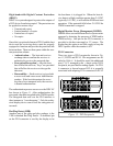
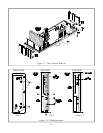
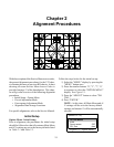
Main Chassis Removal
Refer to Figure 1-2 to remove the Main Chassis.
1. Undo the cable wire ties to the Front Panel,
Speakers, CRTs, etc.
2. Unplug the Card Reader USB and 1394
cables from the DM module.
2. Remove screw (a) securing the Main Chassis
[and screws (b) in models WS-55813 and
WS-65813] .
3. Release the Chassis Locks on each side of
the chassis.
4. Slide the Chassis out the rear of the unit.
5. Tilt upward to access the bottom of the main
chassis.
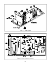
DM Replacement
Refer to Figure 1-3 to replace the DM assembly.
1. Unplug the Card Reader USB and 1394
cables from the DM module, and refer to the
Chassis Removal Procedure to slide the
chassis towards the rear of the set.
2. Remove screws (a), to remove the DM Rear
Panel, Step 1.
3. Remove screws (a) and (b) to remove the
DM Module Cover, Step 2.
3. Remove the E2P module from the original
DM and plug it into the replacement DM.
5. Plug the DM module securely into the PCB-
DTV-TUNER.
6. Check operation before installing the DM
Cover, Step 3.
• Insert insulation (cardboard) between the
Demodulator Ground Spring and the
DM.
• Plug the set in and check the operation.
• If O.K., unplug the set and install the
DM Cover.