


3-8
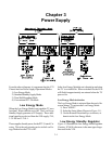
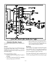
the oscillator drive to the FET. The PWM is automati-
cally changed to maintain a constant 110V source.
Five supplies are directly generated by signal from
T9A50, 210V, 110V, 17V, +24V and -24V.
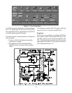
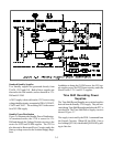
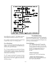
Power Distributions
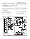
Figure 3-10 shows the Switched Supplies Power Dis-
tribution. The 110V supplies power to DBF, Horizon-
tal Drive, HV and SVM circuitry.
The +24 source supplies power to the Vertical Output,
X-Protect and Convergence circuitry. It also generates
the 12V-MAIN supply that is dedicated to HV Drive
and Deflection Loss circuitry.
The -24V supply is used in the Convergence circuitry,
and is the source for the -20V supply used in the CRT
Drive circuitry. The 210V supply is also used in the
CRT Drive circuits.
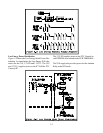
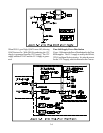
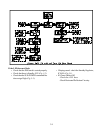
Troubleshooting
The most common symptom due to Power Supply prob-
lems is "The TV Will Not Turn On". The Flow Chart in
Figure 3-11 may be of some help in isolating the cause
of a "Won't Turn On Problem".
If the LED flashes:
• For 1 minute before the TV turns On:
This is normal, it takes about 1 minute for the
circuitry to Boot Up. Boot Up occurs the first
time the TV is plugged, and if in the Low
Energy mode when the Power button is
pressed.
• Flashes Continuously
It indicates the TV µPC is not functioning.
• Flashes-Stops-Flashes-Stops-etc.
It indicates a loss of communication between
the TV µPC and the DM µPC.