


4-3
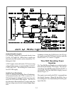
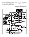
Both the µPCs have the ability to reset each other if
communication is lost. IC7C30 serves as a Reset inter-
face between the two µPCs and the front panel Reset
button. If the TV µPC gets no response from the DM,
it outputs a High at pin 73 of IC7A00. The High is
routed through IC7C30 and drives the DM-RESET in-
put at pin 15 of the TC connector High.
Conversely, if the DM µPC gets no response from
IC7A00, the DM outputs a Low at pin 18 of the VC
connector. The Low, through IC7C30 activates a TV
Reset pulse from IC7C70.
When the front panel recessed Reset button is pressed,
both µPCs are reset through IC7C30.
IC7A00 also outputs reset pulses for the Convergence
Generator, Audio Control, 3DYC and MLink circuitry.
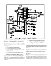
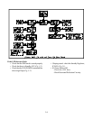
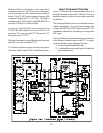
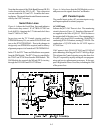
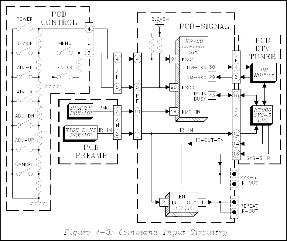
Input Command Circuitry
Figure 4-3 illustrates the Command Input circuit. It is
basically the same as that in the V19 and V21 so an in
depth description is only necessary on those parts that
are different.
The front panel Buttons are in a conventional resistive
ladder configuration. Pressing a button changes the
voltage at the KSC0 or KSC1 input of the µPC. The
command is identified by the change in voltage at the
KSC input.
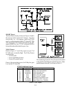
There are differences in the Remote input circuitry due
to the Remote Learning feature of the V23. As in pre-
vious models there are two Remote Preamps:
1) A conventional Mitsubishi Preamp.
2) A wideband Preamp amplifying the IR signals of
most manufacturers.