


8-1
Chapter 8
Sound Circuitry
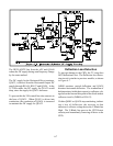
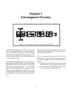
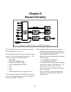
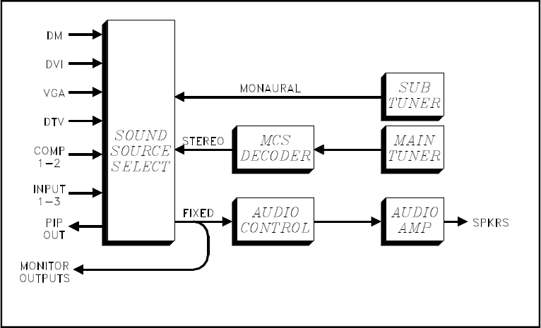
The V23 Sound Circuitry is shown above in the Over-
all Block Diagram, Figure 8-1.
The Sound Source Select circuitry selects the sound
source for both the main and sub pictures. The
sources correspond to the Video Inputs:
• Main Tuner
• Sub Tuner (monaural only)
• Three External NTSC Inputs
• Two Component Inputs (DVD)
• DTV
• DVI
• VGA
• DM (Analog Audio from a digital source)
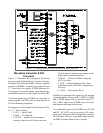
The sound signal from the DM Module is initially
received in a digital format, from the ATSC/QAM
Tuner or the IEEE 1394 inputs.
The remainder of the circuitry is conventional:
• MCS Decoder circuitry decodes the Main
Tuner sound signal, generating mono, stereo,
or SAP signals when broadcast.
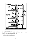
• Main picture sound from the Select circuitry
takes two paths:
1) To Audio Control circuitry
2) To the Monitor Outputs
• The Audio Control circuitry performs adjust-
ments to the Volume, Treble, Bass, etc. The
outputs from Audio Control circuit are
directed to the Audio Amplifier, and then to
the set’s speakers.
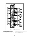
• Sub picture (PIP) sound, from the Source
Select circuit is directed to the PIP Sound
Output Jacks.
Figure 8-1: Sound Circuitry - Overall Block Diagram