


5-4
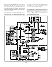
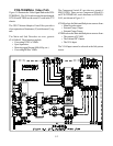
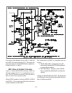
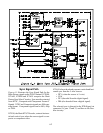
The outputs of the Doubler circuit, ASIC-Y, ASIC-Pb
and ASIC-Pr are directed to the VCJ. The signals are
processed in the VCJ and CRT RGB drive signals are
output at pins 64, 63, and 62.
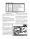
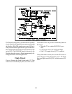
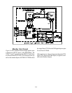
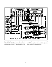
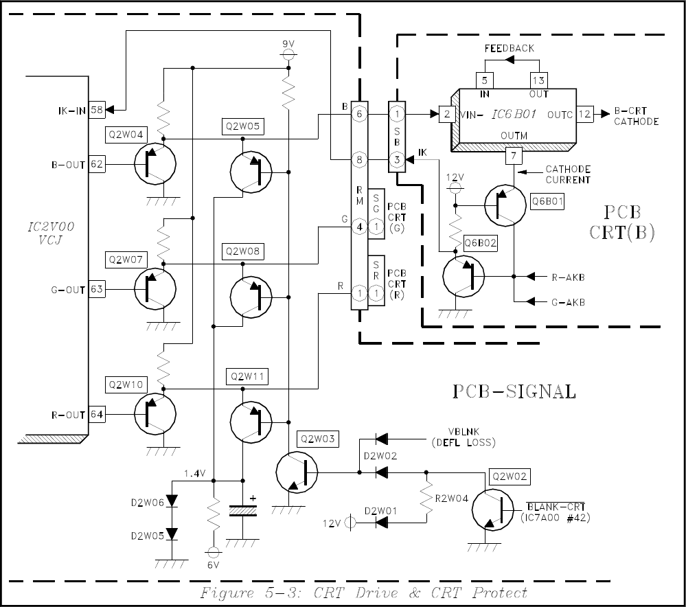
CRT Drive & Protect Circuitry
Figure 5-3 shows the CRT Drive circuitry. Since it is
the same as that in the V21, no explanation is neces-
sary. The CRT Protection circuitry is also the same as
the V21, but a review may be in order.
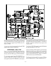
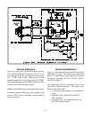
When Q2W03 conducts, it turn On Q2W05, Q2W08
and Q2W11. The conduction of the three transistors
removes RGB drive to the CRTS.
The conduction of Q2W03 is controlled from two
sources:
1) The BLANK-CRT command from the µPC,
momentarily blanking the CRTs during channel
or input selection changes.
2) The VBLNK line. The logic on the VBLNK
line is controlled by Deflection Loss Detection
circuitry.
A High on VBLNK blanks the CRTs. The Deflection
Loss Detection circuitry is discussed in detail in the Sec-
tion on Deflection and HV.