


7-2
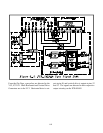
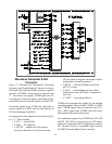
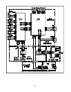
Waveform Generator & D/A
Converter
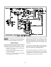
Figure 7-2 illustrates the Convergence Waveform
Generator and Digital/Analog Converter circuitry.
Horizontal Sync from the doubler circuitry is applied
to pin 34 of IC8D00. Vertical Sync is applied to pin
27. From these two signals, IC8D00 generates six
Convergence Correction signals, consisting of hori-
zontal and vertical correction signals for each CRT.
Correction signals from IC8D00 are converted to
analog signals in IC8E03 and are then directed to
LPF and Summing Amplifiers.
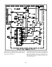
Convergence Control signals are also shown in Fig-
ure 7-2. These include:
• C-SCL … Serial Clock
• C-SDA … I
2
C Data line
• C-MUTE … disables the Convergence
circuitry when the set is first powered on,
off, and when exiting the convergence mode
(when data is stored in memory).
• C-BUSY … Allows IC8D00 to notify the
µPC if it is busy.
• C-ACK … Acknowledgment line, allows
notification to the µPC that a command was
received.
• C—RST … Convergence Reset
IC8D00 also generates the signals for the internal
crosshatch pattern. These are the C-OSDR, C-OSDG
and C-OSDB signals that are directed to the VCJ.
The C-BLK signal from IC8D00 times the cross-
hatch pattern insertion in the picture.
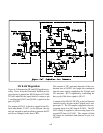
Two additional signals from IC8D00 are HV-ADJ
and DF. HV-ADJ is set by the service HV adjust-
ment and is directed to the HV Regulation circuitry.
DF (Dynamic Focus) is a parabolic signal used by
the DBF (Dynamic Beam Focus Circuitry).
Figure 7-2: Convergence Waveform Generator & D/A Converter