


7-1
Chapter 7
Convergence Circuitry
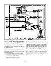
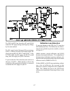
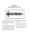
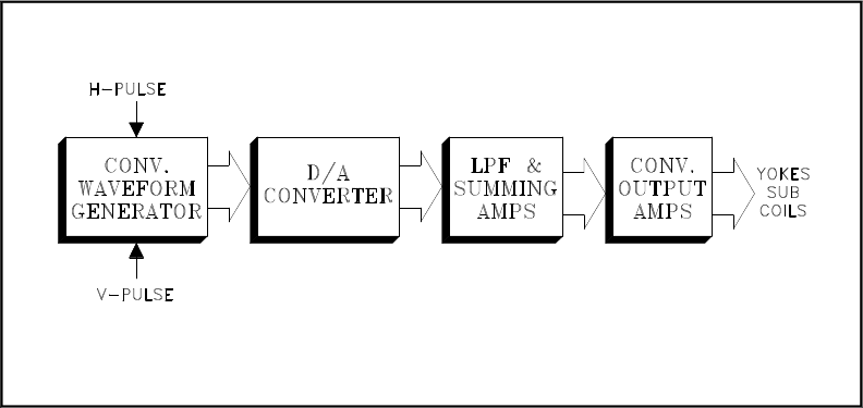
The Overall Block Diagram in Figure 7-1 shows the
the V23 Convergence Circuitry.. A Waveform Gen-
erator generates the convergence correction signals
timed from horizontal and vertical sync pulses. The
correction signals from the Waveform Generator are
in a serial digital format.
The following Digital/Analog Converter changes the
digital signals to analog signals. The analog signals
from the D/A Converter are directed LPF (Low Pass
Filter) and Summing Amplifiers. Any remaining
high frequency digital signals are removed and the
analog correction signals are amplified. Green cor-
rection signals are added to the red and blue signals
in the Amplifiers, hence the name Summing Ampli-
fiers.
The correction signals are amplified by Output Am-
plifiers and are directed to the sub coils in their re-
spective Deflection Yokes.
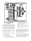
This is the same basic circuitry used in the last few
chassis types. There are only two major differences
in V23 Convergence circuitry compared to that in
the V21.
1) In the V23, the Waveform Generator is on the
PCB-SIGNAL, not on a separate plug-in PCB.
2) Two Convergence Output ICs are used in the
V23, only one was used in the V19.
Figure 7-1: Convergence Circuitry - Overall Block Diagram