


4-2
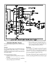
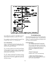
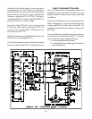
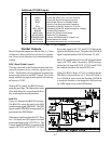
we are not showing the details of the DM circuitry. Fig-
ure 4-1 shows only the DC supplies and Reset signal
going to the DM module.
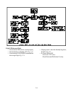
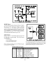
Reset Circuitry
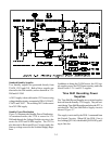
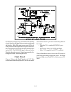
Figure 4-2 illustrates the Reset circuitry in more detail.
The normal and Reset logic are shown in the diagram.
IC7C70 is the Reset IC. A Low from pin 1 resets the
TV µPC. IC7C70 is a Watch Dog type of Reset IC
that monitors the µPC’s operation. It has an internal
counter that is continually reset by pulses from the µPC,
input at pin 4 of the IC. If the µPC locks up, no pulses
are generated. The counter reaches its maximum count
and a reset pulse is output at pin 1 to reset the µPC.