


4-1
Chapter 4
Control Circuitry
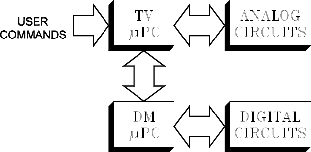
As in the two earlier integrated HDTV chassis, V19
and V21, the V23 uses two Microprocessors in the
Control circuitry.
1) TV µPC … controlling the analog circuitry.
2) DM µPC … controlling the digital circuitry.
The two µPCs constantly communicate with each other.
User commands are input to the TV µPC. Digital com-
mands are forwarded from the TV µPC to the DM µPC.
The TV µPC generates Control commands from two
sources.:
1) User commands from the front panel or remote
control
2) Commands from the DM µPC.
Even though circuitry is becoming more complex, the
same basic requirements must be met for a µPC to op-
erate.
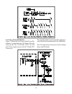
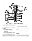
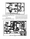
Basic µPC Requirements
Figure 4-1 illustrates the four basic requirements for
the TV µPC operation in the V23.
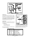
1) DC Supply … 3.3V-ES and 5VS.
2) Ground Returns … pins 8, 9 and 14.
3) Timing Signal … 15 mHz Clock Oscillator
4) Reset circuitry … sets the µPC to its nominal
starting point
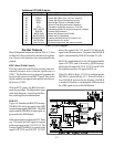
There is similar circuitry for the DM µPC. Since the
DM Module is considered a replaceable component