


6-9
DO NOT measure the HV-DC-FB voltage at pin 13
of the T5A51. The meter may load down the inter-
nal resistive divider, resulting in excessive HV.
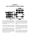
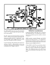
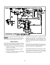
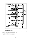
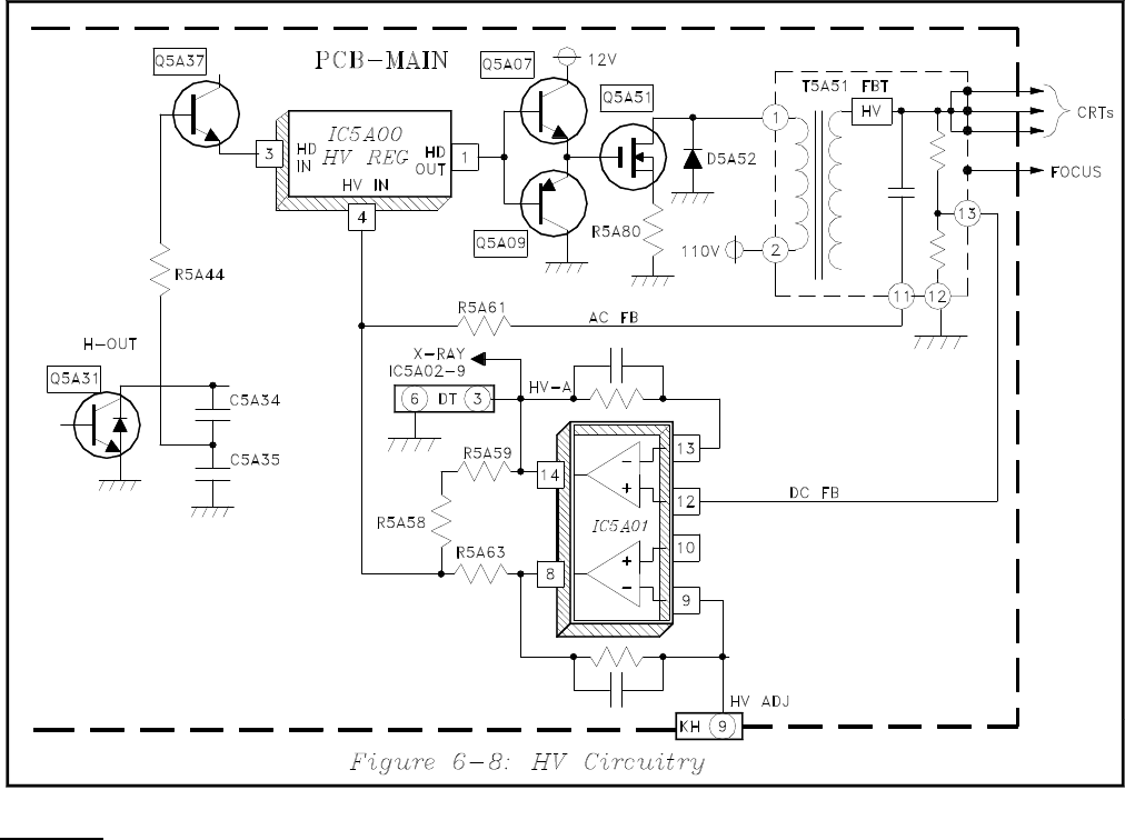
X-Ray Protect
X-Ray Protect circuitry is the basically the same as
in previous models, as shown in Figure 5. The X-
Ray Protect circuit in the V20 monitors three items:
1) Q5A51 (HV Output) current, by monitoring
Q5A51 source voltage.
2) Excessive HV, by monitoring the rectified
voltage from D5A57.
3) Excessive CRT Beam current, by monitoring
the voltage at pin 8 for T5A51.
Each of the monitored sources is applied to an input
of an OP-Amp in IC5A02. The second input of each
OP-Amp is connected to a specific reference. The
outputs of all three Op-Amps are tied together at the
X-Ray line.
The X-Ray line is normally High. If any of the moni-
tored sources exceeds its’ specific reference the X-
Ray line is pulled Low, shutting Off the TV.
The connection from the source of Q5A51 to pin 5
of IC5A00 provides further protection. If the source
voltage becomes excessive (excess current), IC5A00
immediately removes all drive to Q5A51.