


2-6
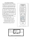
1) Use AUDIO button to select a Sub
Function
2) Use the VIDEO button to select an
Adjustment Item.
3) Use the ADJUST buttons to change
data.
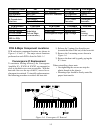
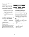
FINE CONV (Press 4)
This mode is used to perform Fine Raster
Correction, and Fine Red and Blue Conver-
gence Adjustments. There are three Sub
Adjustment Functions, selected with the
AUDIO button:
• FINE GREEN .... a Green Crosshatch is
displayed, to make Fine Raster Corrections.
• FINE RED .... a White Crosshatch is dis-
played, to make Fine Red Convergence
Adjustments.
• FINE BLUE .... a White Crosshatch is
displayed, to make Fine Blue Convergence
Adjustments.
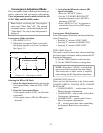
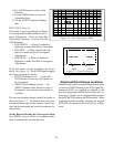
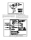
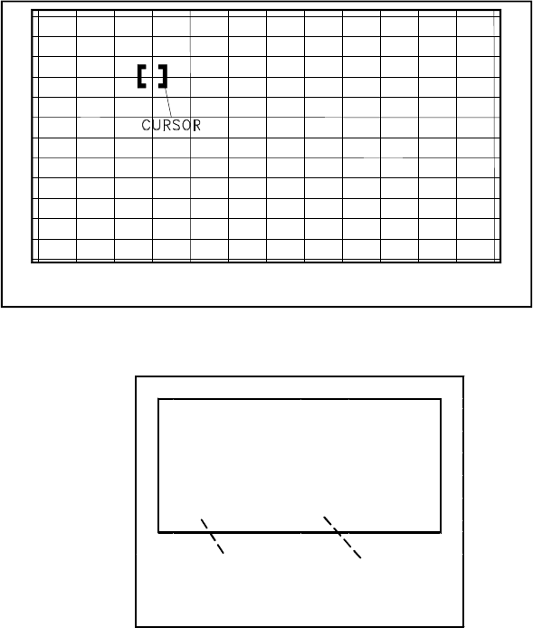
In the Fine mode a Cursor is added to the Cross-
hatch. See Figure 2-6. The ENTER button toggles
the Cursor between two modes:
• MOVE (blinking Cursor) .... use the AD-
JUST buttons to select any of 64 points on
the Crosshatch.
• ADJUST (Non blinking Cursor) .... the
ADJUST buttons adjust the active color at
the current Cursor position, horizontally or
vertically.
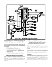
The on-screen display changes in the Fine mode, as
shown in Figure 2-7. The display shows the verti-
cal and horizontal data for the current Cursor Posi-
tion, and the horizontal and vertical coordinates for
that position.
Saving Data and Exiting the Convergence Mode
Press MENU twice to exit the Convergence mode.
Data is automatically saved at this time.
Figure 2-6: Fine Convergence Mode
V23
CONV FINE
GREEN
V13
H-4
SD
VERTICAL
DATA
HORIZ.
DATA
Figure 2-7: Fine Convergence
Alignment Data Storage Locations
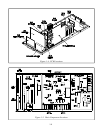
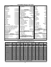
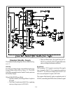
Data accessed in the Convergence Adjustment Mode
is stored in IC8D01 located on the PCB-Signal. Re-
placement PCB’s are supplied pre-aligned so that
only fine adjustments should be necessary after re-
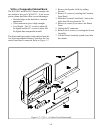
placement. All other service alignment data is stored
on the PCB-E2P located on the DM assembly. When
replacing the DM assembly, retaining the original
PCB-E2P will minimize the need for any realign-
ment.