


1-5
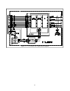
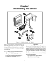
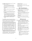
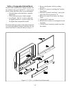
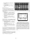
PCB & Major Component Locations
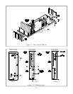
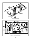
PCB and major component locations are shown in
Figures 1-4 and 1-5. The major circuit functions
performed on each PCB is listed in Table 1-1.
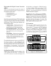
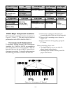
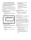
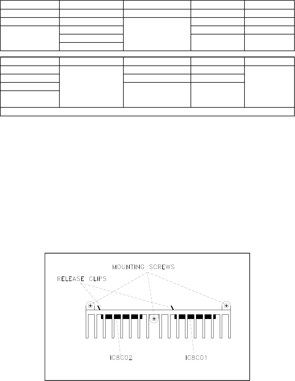
Convergence IC Replacement
To maximize cooling efficiency, the Convergence
Amplifier ICs, IC8C01 & IC8C02, are mounted as
close to the back cover vents as possible. With the
heat sink fins over the top of the IC, access for re-
placement is restricted. To simplify replacement use
the following procedure to remove the heat sink.
Figure 1-6: Convergence IC Removal
1) Release the 2 spring clips from the rear
(towards the front of the set) of the heat sink.
2) Remove the 3 mounting screws shown in
Figure 1-6.
3) Remove the heat sink by gently prying the
IC’s loose.
When reinstalling, please note:
• Overtightening the screws can strip the
plastic threads in the chassis.
• Mounting clips should be firmly seated for
proper heat transfer.
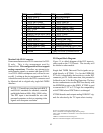
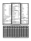
PCB-DTV Tuner DM PCB-MLINK PCB-Terminal PCB-Signal
IR Learning
NetCommand
DVI Decoder
A/V Inputs
Control uPC
DM Interface IEEE1394 RS-232C Interface A/V Selection Tuning
DTV Tuner Card Viewer 3D-Y/C VCJ
& Demodulator OSD-Menus
NTSC Video
Convergence
Interface Digital uPC Control Decoders Generator
PCB-Doubler PCB-SVM PCB-Power PCB-Main PCB-DBF
PIP-POP Scan Velocity Power Supplies Horizontal Defl. Dynamic
Picture Format Modulation Audio Amp. Vertical Defl. Beam
3:2 Pull Down (Picture Edge Convergence Amps. High Voltage Forming
Line Double
Enhancement)
(Corner Focus)
480i to 480p
Table 1-1: PCB Functions