


27
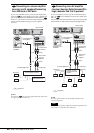
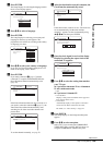
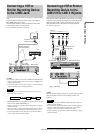
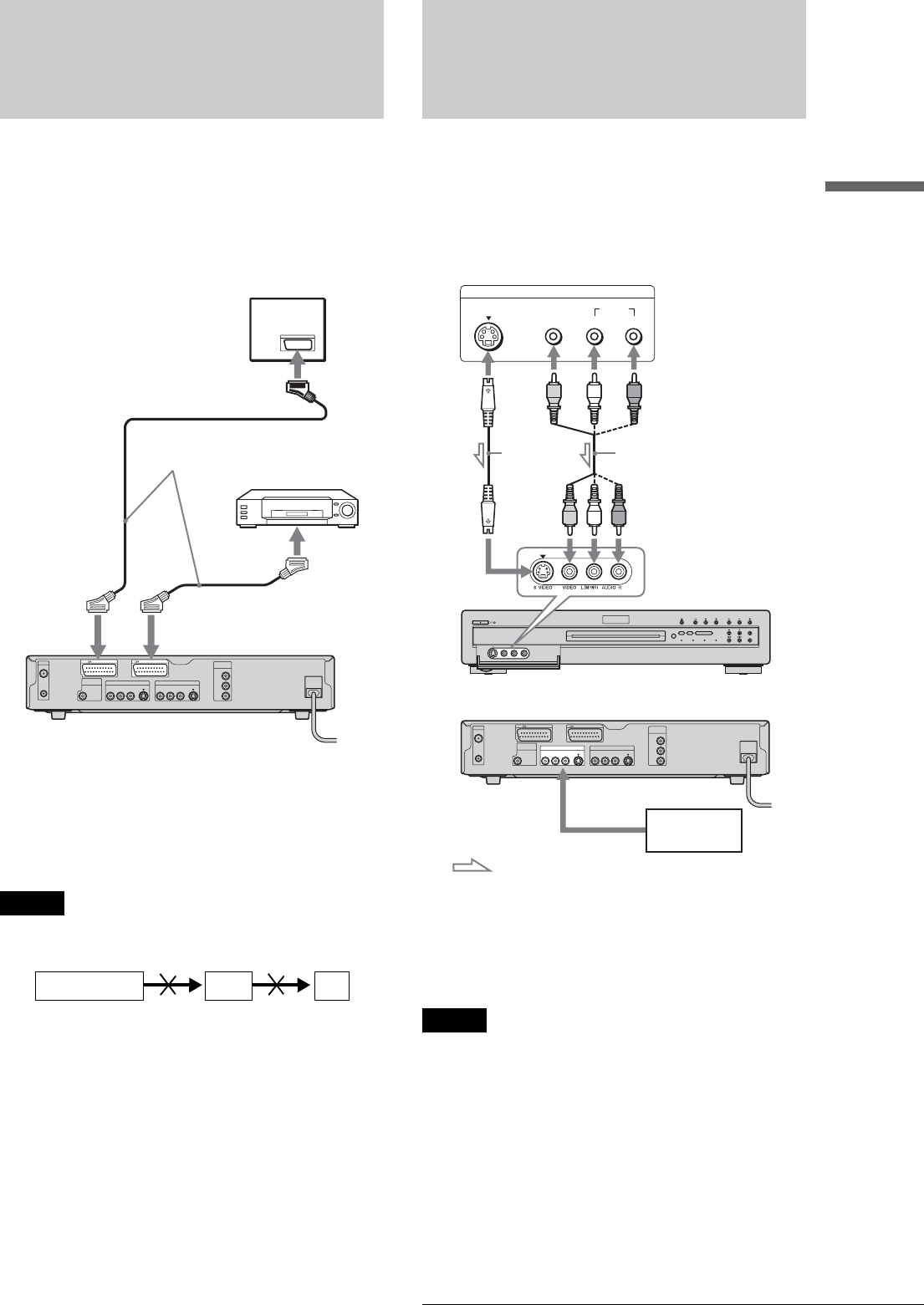
Connecting a VCR or Similar Recording Device to the LINE3 Jack
Basic Hookups and Settings
Connecting a VCR or
Similar Recording Device
to the LINE3 Jack
You can use this recorder as the source player or as the recording
deck.
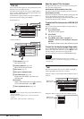
Connect a VCR or similar recording device to the LINE 3/
DECODER jack of this recorder.
Disconnect the recorder’s mains lead from the mains when
connecting the VCR or recording device.
To record on this recorder, see page 48.
z Hints
• If you are using another recorder with S VIDEO and AUDIO IN/OUT
jacks, you can connect those jacks to this recorder’s S VIDEO and R-
AUDIO-L IN/OUT jacks.
• If you are using this recorder as the source player, see the instructions
of the connected device for recording instructions.
Notes
• If you pass the recorder signals via the VCR, you may not receive a
clear image on the TV screen.
• SMARTLINK features are not available for devices connected via the
DVD recorder’s LINE 3/DECODER jack.
• Pictures containing copy protection signals that prohibit any copying
cannot be recorded.
• When you record to a VCR from this DVD recorder, do not switch the
input source to TV by pressing the TV/DVD button on the remote.
• If you disconnect the recorder’s mains lead, you will not be able to
view the signals from the connected VCR.
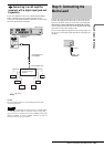
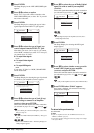
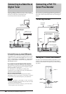
Connecting a VCR or Similar
Recording Device to the
LINE 2 IN or LINE 4 IN jacks
You can connect other equipment (e.g. a VCR or video camera)
and output the audio/video signals to the recorder for recording.
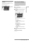
Connect a VCR or similar recording device to the LINE 2 IN or
LINE 4 IN jacks of this recorder. Disconnect the recorder’s
mains lead from the AC outlet when connecting the tuner.
To record, see page 48.
z Hint
When the connected equipment outputs only monaural sound, use audio
cables that distribute monaural sounds to left/right channels (not
supplied).
Notes
• Do not connect the yellow LINE IN (VIDEO) jack when using an S
VIDEO cord (not supplied).
• Do not connect the output jack of this recorder to another equipment’s
input jack with the other equipment’s output jack connected to the
input jack of this recorder. Noise (feedback) may result.
• Pictures containing copy protection signals that prohibit any copying
cannot be recorded.
~
AC IN
LINE 2 OUT
S VIDEOVIDEOR-AUDIO-L
COMPONENT
VIDEO OUT
C
B
Y
C
R
LINE 4 IN
S VIDEOVIDEOR-AUDIO-L
LINE 1 - TV
AERIAL
IN
OUT
LINE 3/DECODER
DIGITAL OUT
PCM/DTS/MPEG/
DOLBY DIGITAL
COAXIAL
TV
to SCART
(EURO AV) input
SCART (EURO AV)
cord (not supplied)
VCR
to i
LINE1-TV
to i LINE
3/DECODER
DVD recorder
VCRDVD recorder TV
OUTPUT
S VIDEO
AUDIO
LR
VIDEO
~
AC IN
LINE 2 OUT
S VIDEOVIDEOR-AUDIO-L
COMPONENT
VIDEO OUT
C
B
Y
C
R
LINE 4 IN
S VIDEOVIDEOR-AUDIO-L
LINE 1 - TV
AERIAL
IN
OUT
LINE 3/DECODER
DIGITAL OUT
PCM/DTS/MPEG/
DOLBY DIGITAL
COAXIAL
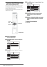
VCR, etc.
DVD recorder (front)
(rear)
Audio/video cord
(not supplied)
S VIDEO
cord (not
supplied)
to LINE 2 IN
: Signal flow
to LINE 4 IN
VCR, etc.