20
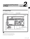
2-1 Control Panel
Chapter 2 Locations and Functions of Parts
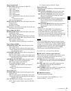
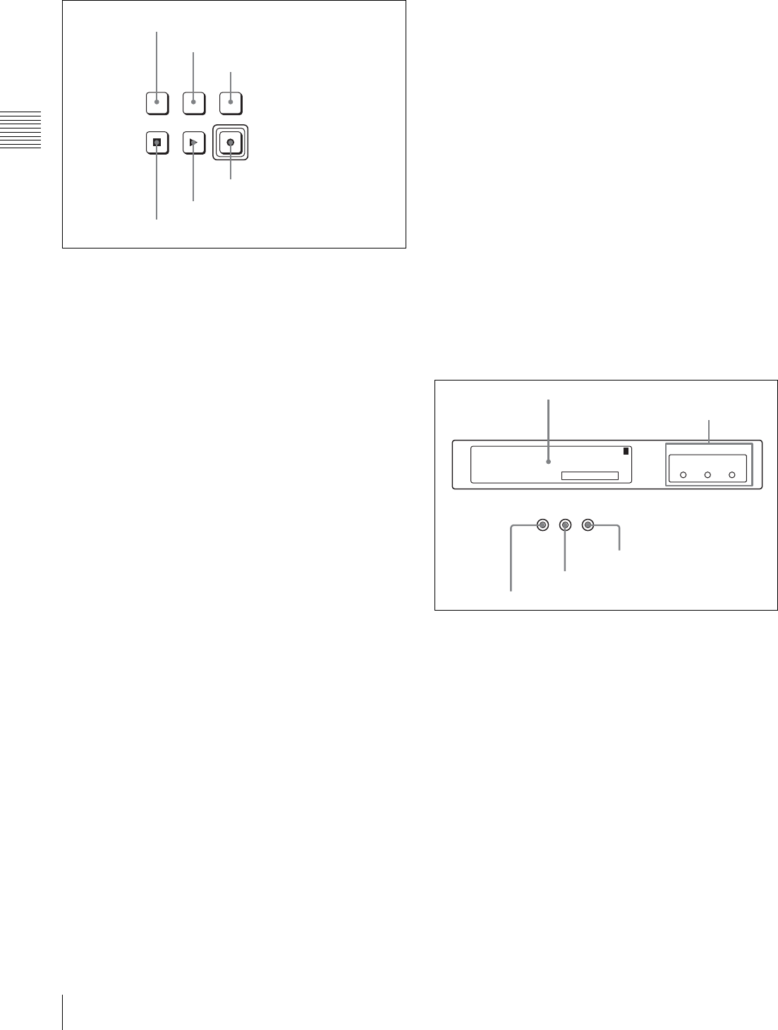
3 Tape transport control section
a STANDBY button
Press this button in other than standby mode to make it
light up and place the VTR in standby mode. The head
drum rotates in standby mode, thereby shortening the time
required for the tape to start.
Press this button while in standby mode to turn the button
off and exit from standby mode. The head drum stops
rotating and the tape tension is released. If the VTR
remains in standby mode for more than eight minutes
(factory setting), standby mode is automatically canceled
in order to safeguard the tape.
b PREROLL button
Press to run the tape to the preroll point (a position factory
set to five seconds before the IN point).
Press this button while holding down the IN, OUT,
AUDIO IN or AUDIO OUT button to cue up the tape at the
corresponding edit point.
For details on changing the preroll time, see “4-2-6
Setting the Preroll Time (PREROLL TIME)” on page 52.
c PREVIEW/REVIEW button
After the edit points are set, press this button to preview,
on the monitor connected to the recorder, the effect of the
edit before it is performed. In this operation, the tape runs,
but no editing is carried out.
If you press this button after carrying out an edit, the
results of the edit are played back on the monitor
connected to the recorder.
d REC/EDIT (recording/edit) button
Press this button while holding down the PLAY button to
start recording.
If you press this button in play mode, manual editing
begins. After setting edit points, if you press this button
while the AUTO button is lit, automatic editing is
performed.
e PLAY button
Press to start playback.
Press this button while holding down the REC/EDIT
button to start recording.
Pressing this button during recording or manual editing
changes the VTR to playback mode.
f STOP button
Press this button to stop recording or playback.
When you insert the cassette, the VTR automatically
enters STBY OFF mode.
The STOP button flashes in the following cases.
•The [F2] (SERVO REF) button in the PF1 menu is set to
“input” but there is no video input signal.
•The [F2] (SERVO REF) button in the PF1 menu is set to
“ext” but there is no external reference video signal.
• The input signal is out of synchronization with the
external reference video signal.
You can change the setting of the VTR SETUP menu item
102 “REFERENCE SYSTEM ALARM” so that the STOP
button will not flash in these cases.
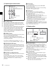
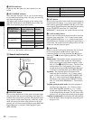
4 Display section
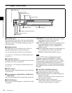
a Information display
The information display shows a number of different
pages. To change the page displayed, with no other items
selected in the menu display (HOME, TC, VIDEO,
AUDIO, PF1, and PF2), turn the MULTI CONTROL knob
while holding it down.
The currently selected page number also appears at the
upper right of the information display.
Page 1: System status
SYS: Shows the recording system information (signal
standard and tape format).
PB: Shows the information recorded on the tape (signal
standard and tape format) while being played back.
FC: Shows the converted signal standard when an HKSR-
5001 board is installed.
TC: Shows the LTC/VITC and DF/NDF settings, or the
time code sent to the external monitor.
PREVIEW/
REVIEW
REC/EDIT
PREROLLSTANDBY
PLAYSTOP
1 STANDBY button
2 PREROLL button
3 PREVIEW/REVIEW button
4 REC/EDIT button
5 PLAY button
6 STOP button
REC
INHIBIT SERVO
EXT
SD
EXT
HD
REF SYNC
INPUT
VIDEO
PREREAD
SYS: 23.98PSF 1080 4:2:2 HDCAM-SR
: -------- ----- ----- --------PB
: 59.94i 1080 4:2:2 FC
T*R 02:01.01:28
1
1 Information display
2 REF SYNC indicators
3 PREREAD indicator
4 SERVO indicator
5 REC INHIBIT indicator


