Teledyne API Model 100AH SO
2
Analyzer Instruction Manual, 02417, Rev. D
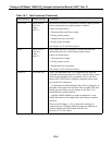
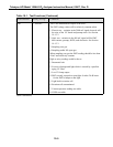
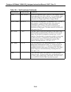
Table 10-1: Test Functions (Continued)
Test Function Factory Set-Up Comment
VACUUM Check value in
Final Test
Values
Table 2-1
Reaction cell pressure is measured to monitor sample pressure
and to compensate any sample pressure variation.
Faults are caused due to:
1. Pump not able to pull the vacuum
2. Faulty pressure sensor
3. Sample line flow restriction
4. Faulty orifice assembly
See Section 10.3.5 Pres/Flow Sensor.
PRES Check value in
Final Test
Values
Table 2-1
Inlet sample pressure is typically 1 In-Hg lower than the
ambient pressure due to the internal pressure drop.
Faults are caused due to:
1. Inlet pressure too high
2. Faulty pressure sensor
3. Sample line flow restriction
See Section 10.3.5 Pres/Flow Sensor.
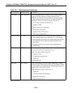
SAMP FL
650 cc/min
±
65
This is the instrument flow. It is computed value from the
upstream and downstream of the orifice. Incorrect flow can be
caused by the plugged orifice, pneumatic leak, or the flow
meter itself. If the orifice is plugged, computed value could
give a false flow indication.
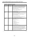
- A rapid method of determining if the orifice is plugged is to
disconnect the sample inlet from the filter assembly cell, then
briefly put your finger over the fittings on the filter. You
should feel the vacuum build up.
- Another reliable method is to attach a rotameter or soap
bubble flowmeter to the sample filter inlet fitting to measure
the flows.
Flow rate will change
±
a few cc/min due to changes in
sample pressure. Changing altitude changes the ambient air
pressure and therefore the sample flowrate. See
Section 10.2.2 Flow Check.
(table continued)
10-4


