Teledyne API Model 100AH SO
2
Analyzer Instruction Manual, 02417, Rev. D
10.3.9 HVPS (High Voltage Power Supply)
The HVPS is located in the interior of the Sensor Module, and is plugged into the PMT tube. It
requires 2 voltage inputs. The first is +15 VDC which powers the supply. The second is the
programming voltage that is generated on the Preamp Board. The test procedure below allows to
test HVPS. Adjustment of the HVPS is covered in the Factory Calibration Procedure in
Section 10.1.6.
To troubleshoot the HVPS:
1. While sampling stable SO
2
gas, record PMT reading and HVPS reading of the TEST
function.
2. Change HVPS voltage about 50V lower than the current setting by adjusting S2 and S1 on
the preamp board. If PMT reading on the display drops about 40±10% from the previous
reading, then HVPS is working properly.
3. If PMT reading does not drop , then do ELECTRIC test per Section 10.1.3.2.
4. If ELECTRIC test is working properly, then do OPTIC test per Section 10.1.3.3.
If all of the above are checked properly, then the problem is either the PMT or HVPS. Check the
HVPS as follows
5. Turn off the instrument.
6. Remove the cover and disconnect the 2 connectors at the front of the SO
2
PMT housing.
7. Remove the end plate from the PMT housing.
8. Remove the HVPS/PMT assembly from the cold block inside the sensor. Unplug the PMT
tube.
9. Re-connect the 7 pin connector to the Sensor end cap, and power-up the instrument.
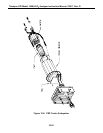
10. Use Figure 10-9 to check the voltages at each pin of the supply, and the overall voltage.
11. Turn off the instrument power, and re-connect the PMT tube, then re-assemble the sensor.
If any faults are found in the test, you must obtain a new HVPS as there are no user serviceable
parts inside the supply.
10-52


