Teledyne API Model 100AH SO
2
Analyzer Instruction Manual, 02417, Rev. D
10.3.8 PMT Cooler
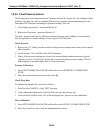
The PMT cooler uses a Thermal Electric Cooler (TEC) supplied with DC current from the
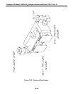
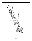
switching power supply in the Power Supply Module. An overall view is shown in Figure 10-8.
The temperature is controlled by a temperature controller circuit located on the Preamp board.
Voltages applied to the cooler element vary from 0.1 to 12 VDC. The input voltage from the
supply is 15 VDC and LED indicates the presence of the voltage. Typical control voltage to the
FET is about 4.5 VDC when PMT temperature is at the 7°C setpoint. At normal room
temperatures the 7°C set point should be maintained within 0.1°C. These voltages can be
measured from the PCB mounted in the fan shroud. The control voltage from the Preamp can be
measured between TP18 and TP11 of the Preamp PCB. Also under normal room temperature
and at the 7°C PMT set point the voltage between TP1 and TP2 will typically measure between
0.15 V - 0.2 V which translates to about 1.5-2 Amp DC current flowing through the Thermal
Electric Cooler (TEC). Following procedures show how to replace the TEC assembly.
1. Remove three screws that hold the sensor assembly (Refer to Figure 2-1. They are located
adjacent to the shipping screws).
2. Remove four screws that hold the fan duct and unplug cable plugs from the fan duct
assembly.
3. Remove four screws holding the heatsink assembly from the PMT housing assembly and
separate these two assembly carefully by pulling heatsink assembly slowly out of the PMT
housing until HVPS module is completely out of the PMT housing (refer to Figure 10-8).
4. Remove two screws from the HVPS module to separate HVPS module from the cooler
block.
5. Pull out PMT, LED, and thermistor carefully from the cooler block. Be careful not to
contaminate the window of the PMT with thermal compound from the thermistor. The PMT
is fragile, so handle carefully.
6. Replace two desiccant bags inside of the PMT housing with new bags.
7. Replace cooler assembly (P/N 01461) and assemble by reversing the above steps.
10-50


