Teledyne API Model 100AH SO
2
Analyzer Instruction Manual, 02417, Rev. D
10.1.5 Test Channel Analog Output
Many of the TEST functions have an analog voltage associated with them. As a diagnostic aid it
is possible to route any one of the various test voltages out the 4th analog output port (see
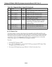
Figure 2-2). Table 10-6 lists the test measurements that may be routed to test channel output. To
route an analog test measurement to test channel output, press SETUP-MORE-DIAG-ENTR and
use the PREV or NEXT buttons to scroll to the TEST CHAN OUTPUT and press ENTR. Press
the PREV or NEXT buttons to scroll to the desired measurement and press ENTR.
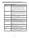
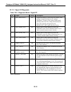
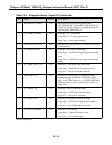
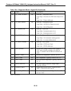
Table 10-6: Test Channel Output
# Name Description Scaled Range
0 NONE
1 PMT READING PMT output 0 - 5000 mV
2 UV READING UV lamp output 0 - 5000 mV
3 SAMPLE PRESS Sample pressure sensor 0 - 40 in-Hg
4 SAMPLE FLOW Sample flow rate 0 - 1000 cc/min.
5 RCELL TEMP Reaction cell temp. sensor
0 - 70
°
C
6 CHASSIS TEMP Inside of chassis temp. sensor
0 - 70
°
C
7 PMT TEMP PMT temp. sensor
0 - 20
°
C
8 DCPS VOLTAGE DC power supply 0 - 5000 mV
9 HVPS VOLTAGE HV power supply sensor 0 - 1000 V
When a measurement other than NONE is selected, an additional test measurement appears on
the display, which has the format "TEST=XXXXX.X MV" and shows the mV value currently
being output to test analog output port.
10-20


