Teledyne API Model 100AH SO
2
Analyzer Instruction Manual, 02417, Rev. D
2.2 Electrical and Pneumatic Connections
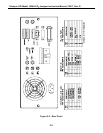
1. Refer to Figure 2-2 to locate the rear panel electrical and pneumatic connections.
2. The pressure of the sample gas at the inlet port should be at atmospheric pressure (±2”Hg).
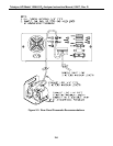
Refer Figure 2-3 and Figure 8-1 for pneumatic system connection.
3. Attach the pump to the “Exhaust Out” port on the instrument rear panel. The exhaust from
the pump also should be vented to a suitable vent at atmospheric pressure. (See Figure 2-3
for exhaust line venting recommendations.)
4. If desired, attach the analog output connections to a strip chart recorder and/or datalogger.
Non-isolated 4-20mA current output is standard. Each 4-20 mA current output should be
connected to one interfacing device only.
5. Connect the power cord to the correct voltage line, then turn to Section 2.3 Initial Operation.
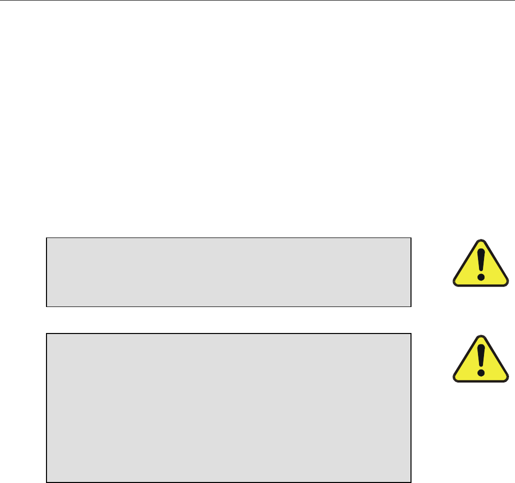
WARNING – Analyzer Exhaust
Danger – Analyzer exhaust may contain high concentration of SO
2
gas. Exhaust properly from the pump pack exhaust to well ventilated
area at atmospheric pressure.
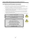
CAUTION
High voltages present inside case.
DO NOT LOOK AT THE UV LAMP.
UV LIGHT COULD CAUSE EYE DAMAGE.
ALWAYS USE SAFETY GLASSES
(PLASTIC GLASSES WILL NO DO).
Connect the exhaust fitting of the pump to a suitable
vent outside of the room.
2-2


