Teledyne API Model 100AH SO
2
Analyzer Instruction Manual, 02417, Rev. D
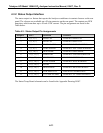
4.3.2 Status Output Interface
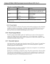
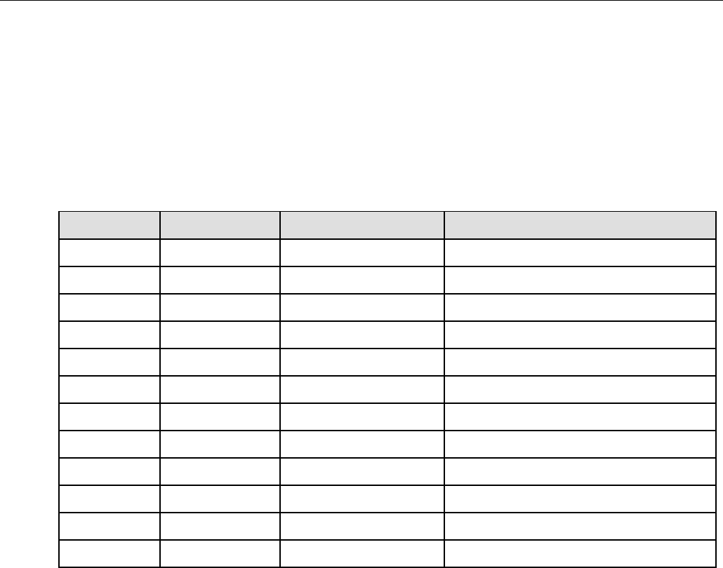
The status output is a feature that reports the Analyzer conditions via contact closures on the rear
panel. The closures are available on a 50 pin connector on the rear panel. The contacts are NPN
transistors which can draw up to 50 mA of DC current. The pin assignments are listed in the
Table below.
Table 4-3: Status Output Pin Assignments
Output # PIN # Definition Condition
1 1 (-), 2 (+) ZERO CAL CLOSED IN ZERO CAL
2 3 (-), 4 (+) SPAN CAL CLOSED IN SPAN CAL
3 5 (-), 6 (+) FLOW ALARM CLOSED IF FLOW WARNING
4 7 (-), 8 (+) TEMP ALARM CLOSED IF ANY TEMP WARNING
5 9 (-), 10 (+) DIAG MODE CLOSED IN DIAG MODE
6 11 (-), 12 (+) POWER OK CLOSED IF SYSTEM POWER OK
7 21 (-), 22 (+) SYSTEM OK CLOSED IF SYSTEM OK
8 19 (-), 20 (+) HVPS ALARM CLOSED IF HVPS WARNING
9 13 (-), 14 (+) SPARE
10 23 (-), 24 (+) HIGH RANGE CLOSED IF HIGH PMT RANGE
11 25 (-), 26 (+) LOW SPAN CAL LOW SPAN CALIBRATION
12 27 (-), 28 (+) UV LAMP ALARM CLOSED IF UV LAMP WARNING
The Status/Temp Board schematic can be found in the Appendix Drawing 01087.
4-11


