


8. Cabling of an OLite rental display
8.2 Data cabling of an OLite rental display
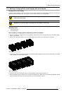
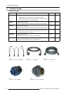
Necessary parts
• Data linking cables.
• One dummy data plug.
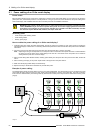
How to realize the data cabling of an OLite rental display ?
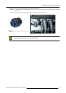
1. Connect the data cable coming from the digitizer with the data input socket of the first tile. The first tile must be one of the tiles
in the corner of the OLite display.
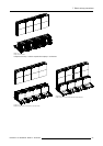
Note: The ma ximum cable length between the digitizer an d the first tile may not exceed 5 meter.
2. Daisy chain the data-linking cables from the data output of previous tile to the data input of the next. This daisy chain linking can
be realized either in horizontal (recommended) or vertical direction starting in a corner of the OLite display.
3. Place a dummy data plug on the data output socket of the last tile in the chain.
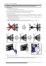
4. Make sure that all plug holder clamps are locked firmly.
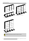
5. Specify in the setup controlling software how the data path is realized (horizontal or vertical) and which tile is the first in the chain.
When using a fiberlink system the fiberlink data connectionis insertedbetweenthe digitizerand the first OLite
tile. The fiberlink receiver is also equipped with Barco’s outdoor connector sockets.
When using an Ambient Environment Controller (AEC) the data connection of the AEC is inserted
between
two OLite tiles. The AEC is also equipped with Barco’s outdoor connector sockets.
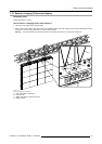
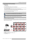
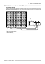
Example of data cabling of an OLite display
The example below shows the data cabling, seen from the rear of an OLite display of four tiles wide and four tiles high. The data
path is realized in a horizontal direction and starts in the lower left corner (seen from the rear). Note that an AEC is included in the
data path. The settings in the control software refer to the display seen from
the front. So, the first tile in the data path has to be
indicated as the lower right tile of the display.
POWER
DATA
OUT
IN
POWER
DATA
OUT
IN
POWER
DATA
OUT
IN
POWER
DATA
OUT
IN
POWER
DATA
OUT
IN
POWER
DATA
OUT
IN
POWER
DATA
OUT
IN
POWER
DATA
OUT
IN
POWER
DATA
OUT
IN
POWER
DATA
OUT
IN
POWER
DATA
OUT
IN
POWER
DATA
OUT
IN
POWER
DATA
OUT
IN
POWER
DATA
OUT
IN
POWER
DATA
OUT
IN
POWER
DATA
OUT
IN
F E
A
D
C
B
POWER
DATA
OUT
IN
DIGITIZER
AEC
LED
WALL
OUT
RS232 IN
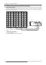
Image 8-3
A Local PC with control software.
B RS232 connection cable between PC and
digitizer (maximum 15 meter).
C Digitizer.
D Data cable between digitizer and first tile (maximum 5 meter).
E Data linking cable between tiles.
F Dummy data plug.
R5976832 OLITE RENTAL DISPLAY 29/05/2007
61