


9. OLite creativity pack
9.4 OLite creativity example
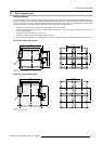
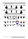
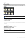
Cabling example
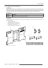
The illustration below shows an interconnection diagram of the OLite 510 modules and the output ports of the control box. The
six output ports of the control box are used and all extension cables in the cabling have a length of 1 meter. Each output port has
the same module cabling configuration. The modules are placed vertically (portrait). Note that the workspace dimensions for this
configuration need to be set, via the control software (Director toolset), to 64 pixels horizontal and 256 pixels vertical.
12 34 56
Image 9-16
Cabling checklist:
1.
Maximum number of modules per output port
16 OLite 510
or
12 OLite 612 modules?
Yes → maximum 10 OLite 510 modules connected to
one port.
2.
Maximum number of modules per control box
64 OLite 510
or
48 OLite 612 modules?
Yes → Only 60 OLite 510 modules connected with the
control box.
3.
Placement angle of modules equal to 0°, 90°, 180° or 270°?
Yes → All modules placed vertically.
4.
Number of module dummy plugs placed in series between
two modules
3?
Yes → 1
5.
Controller - module distance
5 meter?
Yes → longest distance is 3 meter (output port 5 and 6).
6.
Module - module distance
5 meter?
Yes → no extension cables used between modules.
74
R5976832 OLITE RENTAL DISPLAY 29/05/2007