


Intel
®
NetStructure
TM
ZT 7102 Chassis Management Module
Hardware Specifications
Technical Product Specification 19
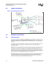
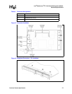
2.3.2 Chassis Sensor Connections
Chassis sensors are connected to the CMM via one two-wire serial bus.
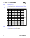
2.3.3 Chassis FRU Device Connections
Chassis sensors are connected to the CMM via one two-wire serial bus. The CMM provides two
2WSB interfaces for chassis FRU modules. Each chassis FRU module is on a dedicated 2WSB in
order to provide redundant access to vital chassis information (e.g., the physical location of the
chassis). The backplane FRU storage device used MUST be an Atmel* AT24C16 or other
24C16-compatible device.
2.3.4 Redundancy
The CMM supports redundant operation with automatic failover under hardware or software
control. The following hardware interfaces exist for the support of redundancy and automatic
failover:
• Cross-connected CMM present inputs (PRES_I#) and outputs (PRES_O#)
• Cross-connected CMM healthy inputs (HLY_I#) and outputs (HLY_O#)
• Cross-connected negotiation inputs (NEG_I) and outputs (NEG_O)
The active CMM monitors its PRES_I# and HLY_I# inputs to determine if it has a healthy, standby
CMM. The active CMM deasserts its HLY_O# output to trigger a failover to the standby CMM.
The cross-connected negotiation signals are used to assure that only one CMM is active at a time.
At anytime, the standby CMM can trigger a failover by driving its NEG_O output low.
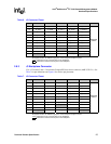
2.4 Power Modules
Power supply sleds are connected to the CMM via two IPMBs. Each power supply sled connects to
one IPMB. Multiple power supplies can share a single IPMB. The CMM also provides independent
DEG#, FAIL#, and INH# signals as defined in PICMG* 2.11 for up to eight power supplies. The
CMM will communicate with intelligent supplies via the IPMBs. Non-intelligent supplies are
supported via the DEG# (degrade), FAIL# (fail), and INH# (inhibit) signals.
The CMM uses INH# rather than EN# to control the power supplies. The EN# pin is grounded on
the backplane to signal to a power supply when it is fully seated in its connector.
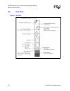
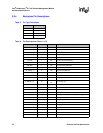
2.5 Fan Modules
Fan trays are connected to the CMM via one two-wire serial bus (2WSB). Intelligent fan trays
communicate with the CMM via the IPMB. To support non-intelligent fan trays, the CMM also
provides independent fan tachometer inputs for up to 16 fans, fan tray present inputs for up to four
fan trays, and four fan speed outputs (four buffered copies of a single PWM). Non-intelligent fan
trays are monitored and controlled via the fan tachometer inputs and the fan speed output.