


Intel
®
NetStructure
TM
ZT 7102 Chassis Management Module
Hardware Specifications
Technical Product Specification 31
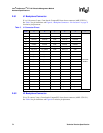
2.9.6 DC Operating Characteristics
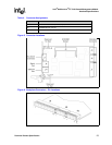
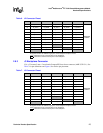
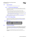
2.10 Onboard Switches
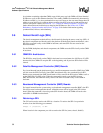
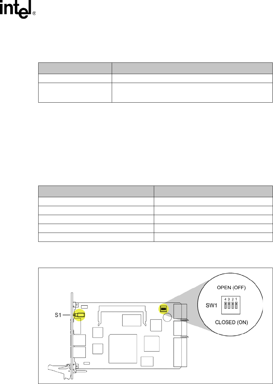
The ZT 7102 contains a push-button switch on the faceplate and one bank of DIP switches on the
component side of the board. See Table 16 for switch identification and functions. Factory default
switch settings are shown in Figure 7.
Note: Where switches are referenced in this chapter, “SWx” refers to the switch number and “-N” refers
to the switch segment (SW1-2 indicates “switch number 1, segment 2”).
See Figure 7 for the default switch configuration.
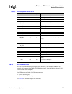
Table 15. DC Operating Characteristics
Signal Range
Supply Voltage, V
CC
4.85 V minimum to 5.25 V maximum
Supply Current, I
CC
1.8 A average (with 733 MHz processor and 32 Mbyte of SDRAM. Peak
(short duration) power supply current may be significantly higher (up to
50%) and varies depending upon the application.
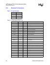
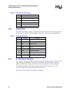
Table 16. Switch Cross Reference Table
Switch Function
S1, “S1 (Alarm Cutoff and Board Reset)” on page 32 Alarm Cutoff and Board Reset
SW1-1, “SW1-1 (Password Reset)” on page 32 Reset Password
SW1-2 Reserved
SW1-3 Reserved
SW1-4 Reserved
Figure 7. Default Switch Configuration