


Intel
®
NetStructure
TM
ZT 7102 Chassis Management Module
CMM Installation and Removal
44 Technical Product Specification
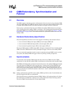
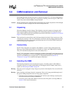
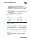
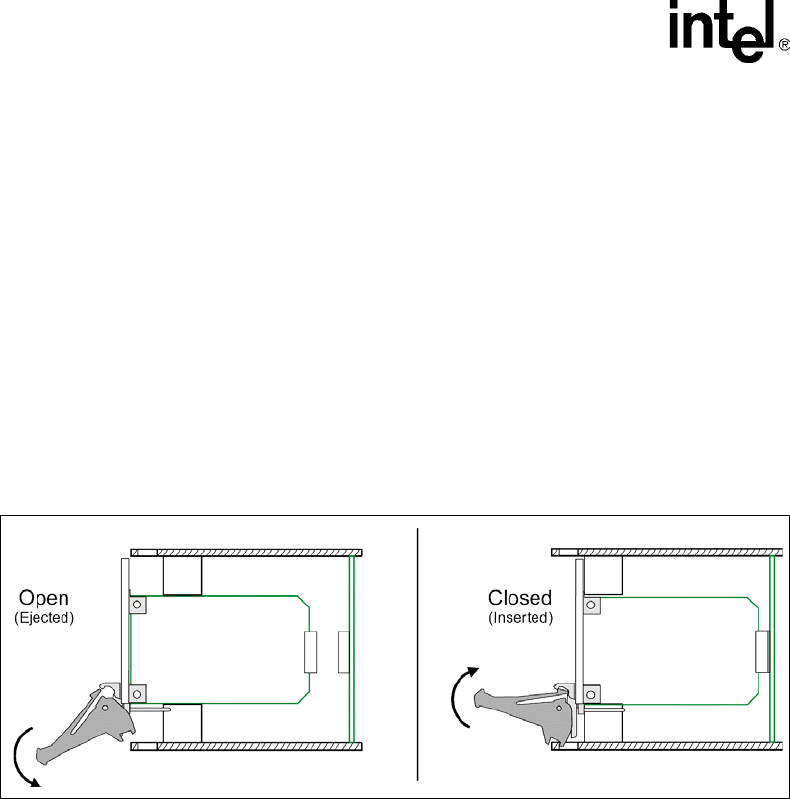
3. Prepare the new/replacement CMM by opening its ejector handle (refer to Figure 8).
4. Carefully align the edges of the board with the card guides in the CMM slot. It may be helpful
to look into the enclosure to verify correct alignment of the rails in the guides.
5. Taking care to keep the board aligned in the guides, slide the board in until the injector/ejector
mechanism engages the retention bar.
6. Simultaneously push in the board and rotate the ejector handle to its closed position (rotate
inward) to seat the backplane connectors.
7. If system power is on, the CMM will boot and its Status LED will light green (active CMM) or
blink green (standby CMM).
8. Screw in the board retention screw to anchor the board in the chassis. This screw is located at
the opposite end of the faceplate from the ejector handle. Refer to Figure 3, “Face Plate” on
page 20 for the screw's location.
9. Use the CMM's Command Line Interface (CLI) to configure the CMM.
5.4 Removing the CMM
Note: The CMM should only be removed when the blue hot swap LED is lit.
In CMM-based systems, the CMM controls power to every slot in the system via BD_SEL#. If a
system's only CMM is removed, all the boards in the system lose power. When hot swapping a
CMM, it performs a controlled shutdown of itself but not the other boards in the system. Therefore,
you should ensure that the entire system is in a “safe” state before removing the CMM. The CMM's
hot swap LED will not light while other boards in the system are powered on.
If a redundant CMM is available, the CMM being removed automatically fails over to the standby
CMM if it is active when the ejector latch is opened. If the active CMM is being removed, the
CMM status light will begin to blink indicating that a failover has occurred. The other CMM’s
status light will be solid green. If a failover does not occur, check the Chassis SEL to see why a
failover cannot occur. In a redundant system, the CMM's removal does not cause a loss of system
power or an interruption in service (you must still wait for the blue hot swap LED to light before
removing the CMM).
If the CMM loses power or is removed suddenly, the CMM's flash memory could become
corrupted. If this happens, restore the board to operation using the instructions in “Updating
Software” on page 127.
Figure 8. Ejector Handle Operation