


Intel
®
NetStructure
TM
ZT 7102 Chassis Management Module
Hardware Specifications
28 Technical Product Specification
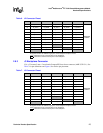
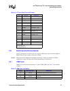
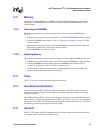
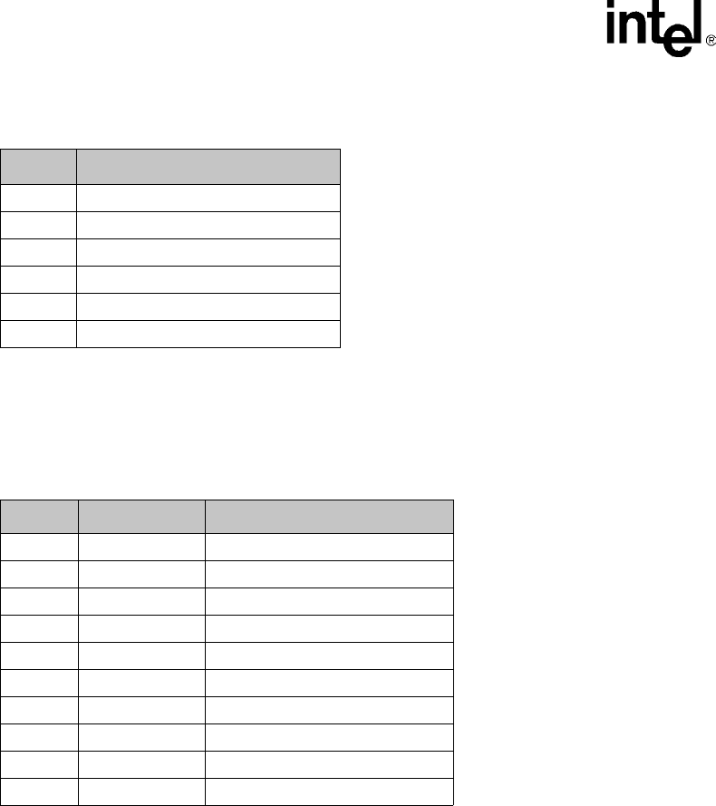
2.8.6 J6 Serial Port
J6 is an RJ-45 connector providing a front-panel RS-232 serial port interface. Serial port signals are
also directed out connector J1 to the backplane. See Table 11 for J6 serial port pin definitions.
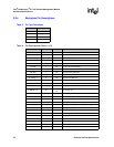
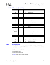
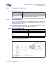
2.8.7 J7 Telco Alarm Connector
J7 is a µDB-15 connector providing a front-panel telco alarm interface. See Table 12 for J7 Telco
alarm connector pin definitions. Contact Intel for information about obtaining a compatible
µDB-15 to DB-15 cable. Contact information is located in Appendix G, “Customer Support”.
For additional information on the Telco Alarm Connector, refer to the Wiring Telco Alarm
Connectors Application Note posted at the following location:
http://www.intel.com/design/network/applnots/273926.htm
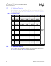
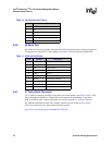
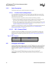
Table 10. JA1 Ethernet Port Pinout
Pin # Description
1TX+
2TX-
3RX+
4,5 Unused pair; terminated on ZT 7102
6RX-
7 Unused pair; terminated on ZT 7102
Table 11. J6 Serial Port Pinout
Pin# Function Description
1 SRTS Serial Request To Send
2 SDTR Serial Data Terminal Ready
3 STx Serial Transmit
4 GND Ground
5 GND Ground
6 SRx Serial Receive
7 SDSR Serial Data Set Ready
8 SCTS Serial Clear to Send
- SRI Serial Ring Indicator (not utilized)
- SCD Serial Carrier Detect (not utilized)