


Intel
®
NetStructure
TM
ZT 7102 Chassis Management Module
CMM Installation and Removal
Technical Product Specification 43
5.0 CMM Installation and Removal
This chapter describes the steps necessary to install and set up the ZT 7102 Chassis Management
Module (CMM). It includes instructions on unpacking, installing, and removing the CMM. Some
systems may come with the CMM(s) already installed.
Caution: The ZT 7102 plugs into a dedicated chassis management slot. System components will be damaged
if a standard 3U board is plugged into the chassis management slot.
5.1 Unpacking
Check the shipping carton for damage. If the shipping carton and contents are damaged, notify
Intel Customer Support. Retain the shipping carton and packing material for inspection by the
carrier. Obtain authorization before returning any product to Intel. Refer to Appendix G, “Customer
Support” for assistance information.
Caution: This board must be protected from static discharge and physical shock. Never remove any of the
socketed parts except at a static-free workstation. Use the anti-static bag shipped with the product
to handle the board. Wear a wrist strap grounded through one of the system's ESD Ground jacks
when servicing system components.
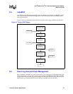
5.2 Connectivity
The ZT 7102 is intended to be installed as the CMM in a system's Chassis Management Slot.
Where two Chassis Management Slots are available in a system, two CMMs may be installed.
(They will automatically negotiate for active and standby roles.)
The ZT 7102 is designed to operate in a backplane providing CompactPCI-style 2 mm hard metric
connectors to the board's J1, J2, and J3 backplane interfaces. The backplane's CMM interfaces are
specific to the CMM and do not support other 3U CompactPCI boards. See Section 2.8,
“Connectors” on page 22 for connector descriptions and pinouts.
5.3 Installing the CMM
The following instructions cover the mechanical aspects of installing the ZT 7102 CMM in a
compatible system. For a better understanding of what happens when a CMM is absent from a
system, see “Removing the CMM” on page 44.
Warning: When the system is plugged in, high voltages are present on the backplane. Do not reach into the
enclosure.
Warning: Static electricity can damage electronic components. Wear a wrist strap grounded through one of
the system's ESD ground jacks when servicing system components.
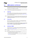
1. Take the necessary precautions to protect the ZT 7102 from static discharge. System power
does not need to be off to install a CMM board.
2. Locate the system's dedicated CMM slot and remove the filler panel or existing CMM (see
Section 5.4 for removal instructions).