Chapter 7 Usage of Various Functions
7-27
Proportional gain
The MASTER-K120S can handle only integer, not the floating point type. Therefore, to enhance the accuracy of
PID operation, the PID8 instruction is designed to input the P_GAIN data as the 100 times scaled up. For
example, if the designated P_GAIN is 98, actual input data of P_GAIN should be 9800. If the designated
P_GAIN is 10.99, input 1099 to the P_GAIN.
Derivative time and integral time
I_TIME and D_TIME are 10 times scaled up. For example, input 18894 if the designated I_TIME value is 1889.4.
The range of actual input is 0 ~ 20000. (it is possible that parameter value designates ‘D’ area also)
Mode command set
In MASTER-K120S, only the following 7 operation modes are available. Other operation modes, such as PD or I,
are not permitted.
No. EN_P EN_I EN_D PWM output Operation
1 1 (enable) 0 (disable) 0 (disable) P operation
2 1 (enable) 1 (enable) 0 (disable) PI operation
3 1 (enable) 1 (enable) 1 (enable)
0 (disable)
PID operation
4 1 (enable) 0 (disable) 0 (disable) P operation/PWM output
5 1 (enable) 1 (enable) 0 (disable) PI operation/PWM output
6 1 (enable) 1 (enable) 1 (enable)
1 (enable)
PID operation/PWM output
7 0 (disable) 0 (disable) 0 (disable) 0 (disable) On/Off operation
PWM set
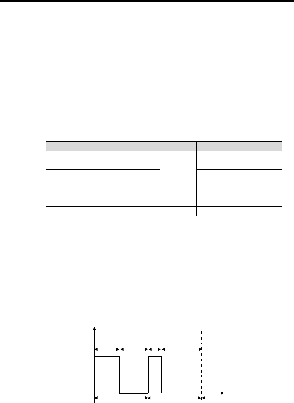
PWM(Pulse Width Modulation) is a output method which changes on-off duty of output pulses by calculated
manipulation value. Fig 7.9 shows example of PWM output. Using PWM output, PID control system can be
constructed easily without D/A conversion module and power regulator.
When PWM is designates , ‘scan time’ item is disabled and ‘PWM’ items can be designated. In this case, scan
time is set to designated PWM output period. The range of PWM output period is 1 ~ 10 seconds, and actual
input range is 10 ~ 100. PWM output point is only available for output contact of main unit.
Example) PWM output period : 1s, Output contact : P40, MV limit range : 0~4000
Time
MV = 2000 MV = 1000
0.5s
On
0.5s
0.25s
0.75s


