Chapter 5 Power Supply / CPU
5 -35
(2) Read RTC data from special register
Description
Special register Area
(Word)
Upper byte Lower byte
Data
(BCD format)
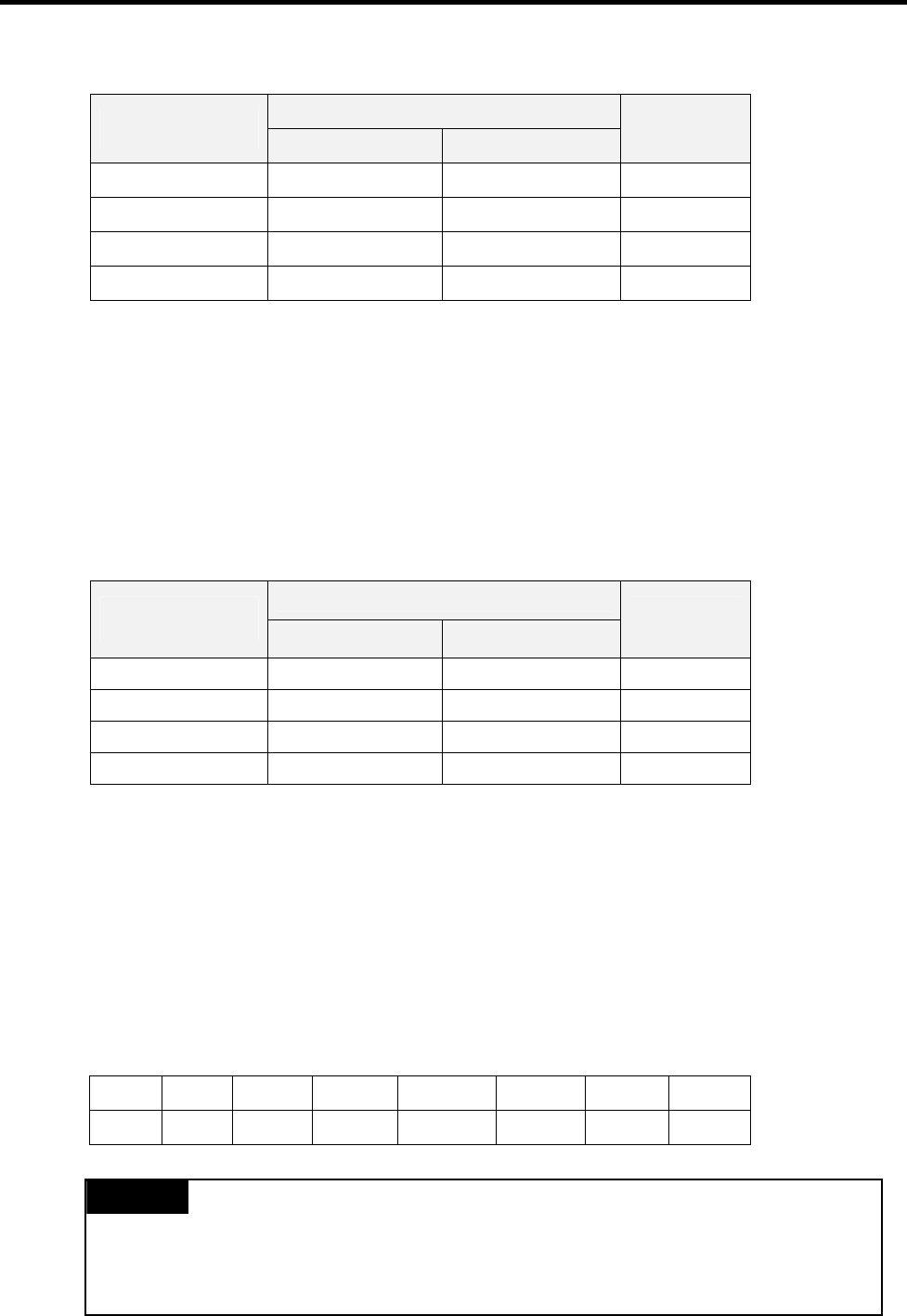
F053 Lower 2 digits of year Month H0207
F054 Day Hour H2313
F055 Minute Second H5020
F056 Higher 2 digits of year Date H2002
Example : 2002. 07. 23. 13:50:20, Tuesday
2) Write RTC data
There is two ways to write new RTC data to the CPU.
The first one is using a graphic loader (KGLWIN). For detailed information, refer the user’s manual of KGLWIN.
The second one is write sequence program. By switching a special bit on, user can replace the current RTC data with the
reset data stored in a specified memory area. The followings are the memory address of preset data and an example
program.
Description
Data register Area
(Word)
Upper byte Lower byte
Data
(BCD format)
D4993 Lower 2 digits of year Month H0207
D4994 Day Hour H1011
D4995 Minute Second h5324
D4996 Higher 2 digits of year Date H2001
Example : 2002. 7. 10. 11:53:24, Monday
* M1904 : RTC data change bit
When the M1904 bit is switched on, the new data in D4993 ~ D4996 will be moved to F53 ~ F56. After data is
moved, M1904 has to be switched off immediately because current data will be updated every scan while
M1904 is on.
3) Date expression
Number 0 1 2 3 4 5 6
Date Sunday Monday Tuesday Wednesday Thursday Friday Saturday
REMARK
1) If RTC stops or error occurs, write new data to the RTC then error is called off.
2) There is no written clock data in the RTC when shipped.
3) Before using RTC module, write clock data to the RTC first


