


109
CHAPTER 11 TROUBLESHOOTING
11
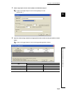
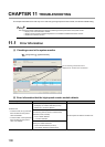
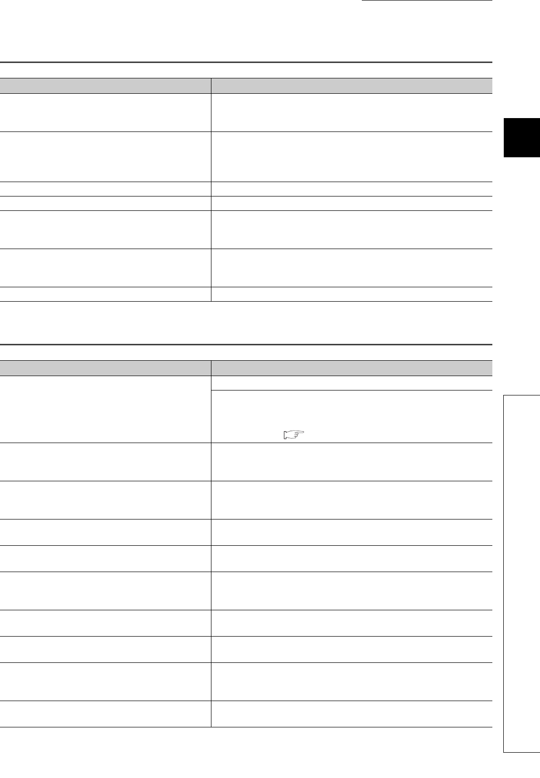
11.2 The Module Does Not Start Counting Operation
11.2 The Module Does Not Start Counting Operation
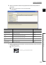
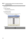
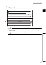
11.3 The Module Does Not Correctly Count Pulses
Check item Action
Is any LED of the CPU module indicating an error?
If the LED indicates an error, refer to the troubleshooting in the manual for the
CPU module used and take corrective actions to restore normal operation of
the CPU module.
Do the A LED and B LED turn on when a voltage is
directly applied to the pulse input terminals for A and B?
If the A LED and B LED turn on, check the external wiring and the encoder,
and make necessary corrections. If they do not turn on, the cause is a
hardware failure. Please consult your local Mitsubishi representative,
explaining a detailed description of the problem.
Is the external wiring for A and B correct? Check the external wiring and make necessary corrections.
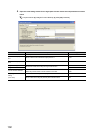
Is CH Count enable command (Y4, YC) on? Turn on CH Count enable command (Y4, YC) using a program.
Is the pulse input method same as the pulse input mode
setting specified in the intelligent function module switch
setting?
Set the pulse input method same as the pulse input mode specified in the
intelligent function module switch setting.
Is CH Counter function selection start command (Y6,
YE) off or is a voltage not applied to the function start input
terminal?
If the count disable function has been selected, turn off CH Counter function
selection start command (Y6, YE) or the function start input terminal.
Is there an overflow error? Execute a preset to clear the overflow error.
Check item Action
Is the external wiring for A and B correct?
Check the external wiring and make necessary corrections.
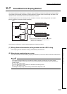
Even in 1-phase input, connecting an ABCOM terminal to a pulse signal can
result in an incorrect count.
Reconnect the ABCOM terminal to the external power supply (5V/12V/24V) or
the GND terminal. ( Page 47, Section 6.3, Page 49, Section 6.4)
Is the maximum speed of the input pulses within the
counting speed range specified in the intelligent function
module switch setting?
Correct the counting speed configured in the intelligent function module switch
setting according to the maximum speed of the input pulses.
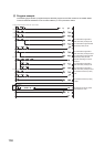
Does the input pulse waveform meet the performance
specifications?
Observe and check the pulse waveform with a synchroscope. If the input
pulse does not meet the performance specifications, input pulses which meet
the performance specifications.
Are the count value data handled in 32-bit signed binary in
the program?
Correct the program so that the count value data are handled in 32-bit signed
binary.
Are shielded twisted pair cables used for the pulse input
lines?
Use shielded twisted pair cables for the pulse input lines.
Is the high-speed counter module affected by noise
through the grounding area?
• Separate the grounding cable of the high-speed counter module from the
grounded part.
• If the high-speed counter module touches the grounded part, separate it.
Are noise reduction measures taken in the control panel
or for noise emitting devices?
Take noise reduction measures such as attaching a CR surge suppressor to
the magnet switch.
Is there a sufficient distance between the high voltage
equipment and the pulse input cables?
Wire the pulse input cables alone when placing them in a duct and keep a
distance of 150mm or more from the power cables in the control panel.
Are the count values of CH1 and CH2 same when the
same number of pulses are input?
If the count values differ, the cause is a hardware failure. Please consult your
local Mitsubishi representative, explaining a detailed description of the
problem.
Was the preset function performed within the count range
of the ring counter? (for the ring counter function only)
Reset the preset value within the count range and perform the preset function
again.