


28
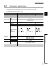
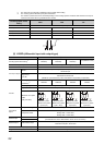
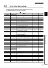
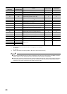
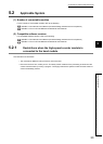
*1 This value is set when the high-speed counter module is powered on or the CPU module is reset.
*2 Whether a value can be read from/written to a program or not is indicated.
R: Readable
W: Writable
*3 Read or write values in 32-bit signed binary. (Be sure to use two words at a time.)
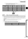
● The system areas listed above and the areas not listed above are used by the system and are not available for users. If
data are written by a user, the performance of the high-speed counter module is not guaranteed.
● Buffer memory data in the high-speed counter module are initialized when the high-speed counter module is powered on
or the CPU module is reset. To save the necessary data, read/write the data by executing the FROM/DFRO/TO/DTO
instructions in the program or performing auto refresh to the device data.
40
28
H
CH2 Overflow detection 0 R
41
29
H
CH2 Counter function selection 0 R/W
42
2A
H
CH2 Sampling/periodic time setting 0 R/W
43
2B
H
CH2 Sampling/periodic counter flag 0 R
44
2C
H
CH2 Latch count value (L)
*3
0R
45
2D
H
CH2 Latch count value (H)
*3
0R
46
2E
H
CH2 Sampling count value (L)
*3
0R
47
2F
H
CH2 Sampling count value (H)
*3
0R
48
30
H
CH2 Periodic pulse count previous value (L)
*3
0R
49
31
H
CH2 Periodic pulse count previous value (H)
*3
0R
50
32
H
CH2 Periodic pulse count present value (L)
*3
0R
51
33
H
CH2 Periodic pulse count present value (H)
*3
0R
52
34
H
CH2 Ring counter lower limit (L)
*3
0R/W
53
35
H
CH2 Ring counter lower limit (H)
*3
0R/W
54
36
H
CH2 Ring counter upper limit (L)
*3
0R/W
55
37
H
CH2 Ring counter upper limit (H)
*3
0R/W
56
38
H
System area to to
63
3F
H
Address
(decimal)
Address
(hexadecimal)
Name
Initial value
*1
Read/write
*2