


47
CHAPTER 6 INSTALLATION AND WIRING
6
6.3 Examples of Wiring Between the High-Speed Counter Module and an Encoder
6.3 Examples of Wiring Between the High-Speed Counter
Module and an Encoder
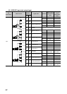
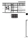
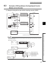
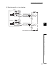
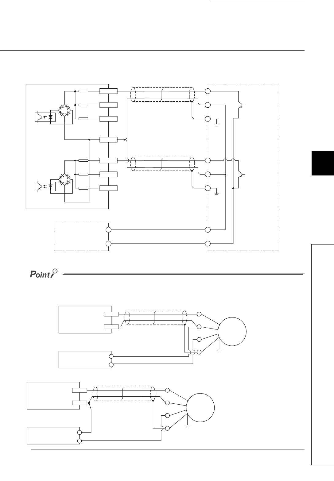
(1) Example of wiring with an open collector output type encoder (24VDC)
For the wiring between the RD62 and an encoder, separate the power supply cables and the signal cables. The following
figures show its examples:
● Example of correct wiring
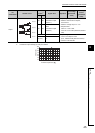
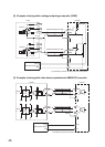
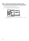
● Example of inappropriate wiring
A20(A13)
24V
B20(B13)
12V
A19(A12)
5V
B19(B12)
ABCOM
Phase A
Shield
OUT
E
+24V
LD62
A18(A11)
24V
B18(B11)
12V
A17(A10)
5V
Phase B
Shield
OUT
E
+24V
0V
+24V
0V
24VDC
External power supply
Shielded twisted pair cable
Shielded twisted pair cable
Encoder
In parentheses, terminal numbers of channel 2 are shown.
24V
ABCOM
LD62
0V
24VDC
External
power supply
OUT
Encoder
+24V
0V
E
Shielded twisted pair cable
Shield
Phase A
24V
ABCOM
LD62
OUT
0V
24VDC
External
power supply
Encoder
+24V
0V
E
Shielded twisted pair cable
Shield
Phase A
Because currents flow in
the same direction in the
shielded twisted pair cable,
canceling effect will be lost
and electromagnetic
induction may occur.