


96
10.2 Connecting the Module to the Head Module
This section describes the system configuration and program examples based on conditions.
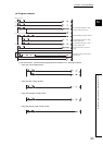
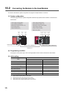
(1) System configuration
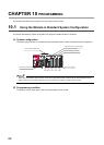
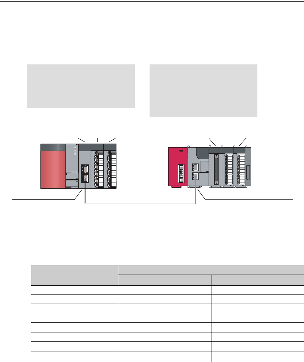
The following figure shows a system configuration where the high-speed counter module is connected to the
head module.
(2) Programming condition
The program counts pulses input to CH1 of the high-speed counter module connected to a head module.
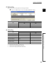
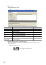
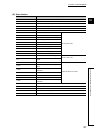
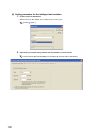
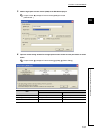
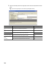
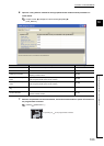
(3) Initial setting
*1 Leave unused channels with the default values.
*2 Set these items when using the ring counter function.
*3 Set this item when using the sampling counter function.
*4 Set this item when using the periodic pulse counter function.
Item
Contents
CH1
CH2
*1
Preset value 2500 0
Coincidence output point No.1 1000 0
Coincidence output point No.2 0 0
Ring counter upper limit
*2
5000 0
Ring counter lower limit
*2
-5000 0
Counter function selection User defined Count Disabling Function
Sampling time setting
*3
10000ms 0
Periodic time setting
*4
5000ms 0
Network No.1
Ethernet cable (1000BASE-T)
CPU module (Q10UDHCPU)
Master/local module (QJ71GF11-T2)
Input module (QX10)
Output module (QY10)
X/Y1000
to
X/Y100F
X/Y1010
to
X/Y101F
X/Y1020
to
X/Y102F
Master station (station No.0)
Intelligent device station (station No.1)
Head module (LJ72GF15-T2)
High-speed counter module (LD62)
Input module (LX40C6)
Output module (LY10R2)
END cover (L6EC)
Power supply module (Q62P) Power supply module (L61P)
X/Y00
to
X/Y1F
X/Y20
to
X/Y2F
X/Y30
to
X/Y3F