


49
CHAPTER 6 INSTALLATION AND WIRING
6
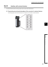
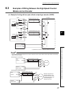
6.4 Examples of Wiring Between a Controller and External Input Terminals
6.4 Examples of Wiring Between a Controller and External
Input Terminals
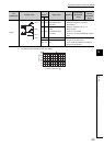
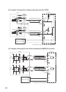
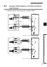
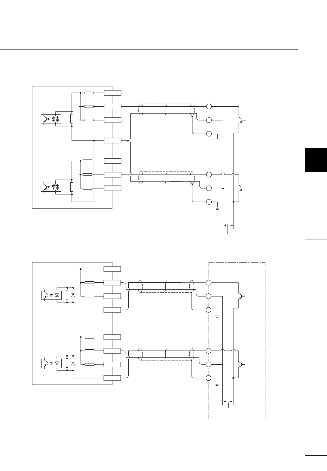
(1) When the controller (sync load type) has a voltage of 12VDC
A18(A12)
24V
B18(B12)
12V
A17(A11)
5V
B17(B11)
PRSTCOM
Preset
Shield
OUT
E
+12V
ControllerLD62D
Shield
OUT
E
+12V
12VDC
A16(A10)
24V
B16(B10)
12V
A15(A09)
5V
B15(B09)
FUNCCOM
Function start
Shielded twisted pair cable
Shielded twisted pair cable
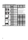
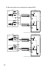
B17(B10)
24V
A16(A09)
12V
B16(B09)
5V
A15(A08)
CTRLCOM
Preset
Shield
OUT
E
+12V
ControllerLD62
Shield
OUT
E
+12V
12VDC
B15(B08)
24V
A14(A07)
12V
B14(B07)
5V
Function start
Shielded twisted pair cable
Shielded twisted pair cable
In parentheses, terminal numbers of channel 2 are shown.
In parentheses, terminal numbers of channel 2 are shown.