


111
CHAPTER 11 TROUBLESHOOTING
11
11.7 Pulse Waveform Shaping Method
11.7 Pulse Waveform Shaping Method
An effective method for pulse shaping is to apply a dummy resistance of several hundreds ohms (/several watts)
across pulse input terminals connected to a pulse generator to increase a load current through the cables. This
method becomes more effective as the load current value increases.
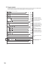
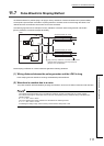
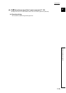
The following figure shows an example of dummy resistance connection when the signal level is at 24VDC.
[Dummy resistance connection example at 24VDC]
Pulse shaping is effective as counter measures against the following situations.
(1) Wiring distance between the pulse generator and the LD62 is long
Pulse shaping removes waveform rounding and stabilizes pulse waveforms.
(2) Waveform is unstable due to a noise
The pulse waveform becomes stable by shaping the waveform, which has an effect on external noise reduction.
The following example describes how to evaluate the resistance constant and rated-power of a dummy resister.
For example, when approx. 30mA load current is set, the corresponding dummy resistance rating is calculated in the
following formula.
R = V I = 24V 30mA = 800
The power applied to the dummy resistance is calculated in the following formula.
P = V I = 24V 30mA = 0.72W
Considering the design margin, select a dummy resistor with the rated power of 2W.
6.8k
1/3W
6.8k
1/3W
Phase
A
Phase
B
Shield
Shielded twisted pair cable
Shield
Shielded twisted pair cable
A20(A13)
B19(B12)
A18(A11)
24V
ABCOM
24V
Apply a dummy resistance of several hundred ohms
(/several watts) across the pulse input terminals
(between 24V and ABCOM).
LD62